
Three-dimensional image display panel structure

Inactive Publication Date: 2013-07-18
CHUNG HYUNIN
View PDF4 Cites 21 Cited by
  • Summary
  • Abstract
  • Description
  • Claims
  • Application Information

AI Technical Summary

Benefits of technology

The present invention aims to provide a stereoscopic image display panel that can expand its effective angle of view while showing various types of flat images as stereoscopic images using an integral photography technique. The patent also aims to remove the image jump phenomenon to secure a clear image on the panel. Different shapes of the convex lens, such as hemisphere or plate, can be used to achieve a wider angle of view. Additionally, a coating layer or a cavity layer can be used instead of a view angle induction mask for higher efficiency. The patent also suggests using a low refractive resin coating layer, a residual image removal mask, or controlling the size, position, or transparency of the perspective blocking stripe or pinhole to improve the display's image quality.

Problems solved by technology

Since a twin lens type image is a stereoscopic image provided by binocular viewpoints (two viewpoints) of one person, it is difficult to correctly display a motion parallax when an observer moves his or her head or a multi-viewpoint stereoscopic image that can be shown to a plurality of people.
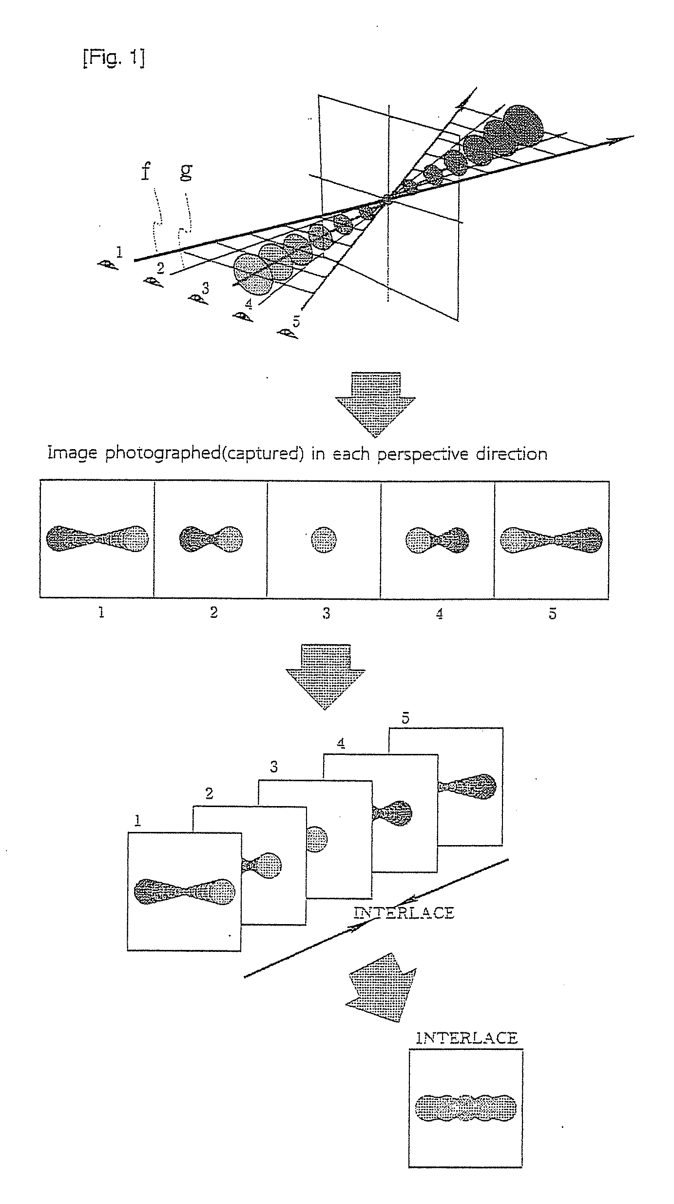
Although a technique of horizontally interlacing an image while a lenticular lens sheet is tilted in the diagonal direction has been tried in order to solve the problem (Korean Laid-opened Patent No. 10-2007-0072590, inventor; Levecu Xavier, Title of the invention; “Lenticular auto-stereoscopic display and method, and auto-stereoscopic image synthesizing method related thereto”), the interlacing process is complex, and it is difficult to align the slope of the lens sheet which forms lenses and vertical and horizontal unit pitches of a minimum pixel which configures an interlaced screen, and thus the technique is difficult to realize.

Method used


Image

  • Three-dimensional image display panel structure
  • Three-dimensional image display panel structure
  • Three-dimensional image display panel structure

Examples


Embodiment Construction

[0099]Reference will now be made in detail to the present embodiments of the present invention, examples of which are illustrated in the accompanying drawings, wherein like reference numerals refer to the like elements throughout. The embodiments are described below in order to explain the present invention by referring to the figures.

[0100]The preferred embodiments of the invention will be hereafter described in detail, with reference to the accompanying drawings.

[0101]FIG. 7 is an exploded perspective view showing a basic structure of the present invention.

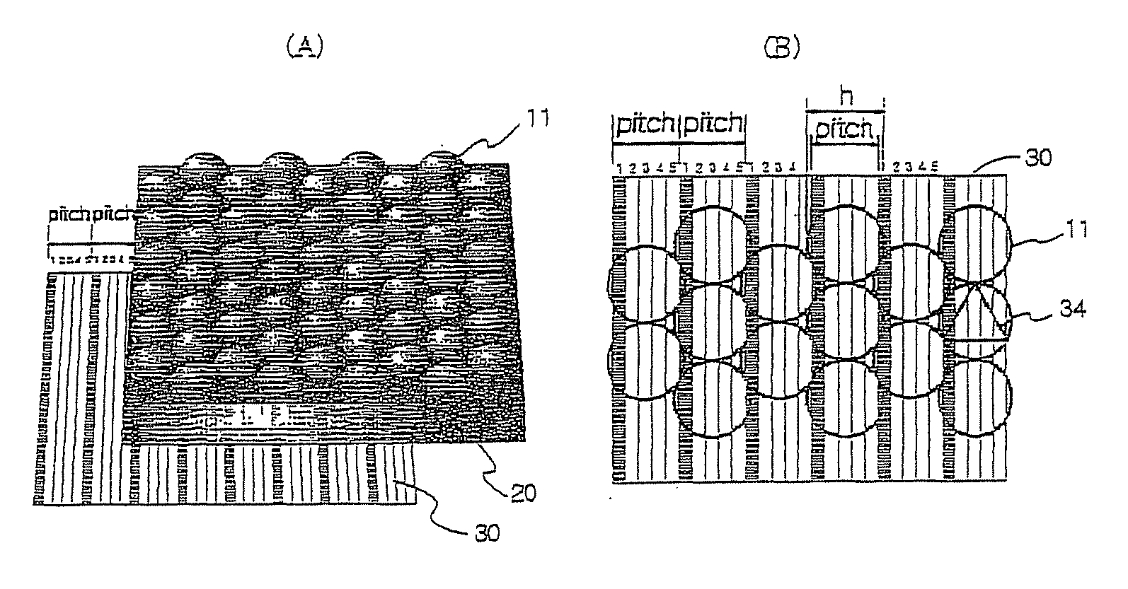
[0102]As shown in the figure, the present invention is configured with a lens array layer 10 on which convex lenses 11 are arranged to be offset each other at a predetermined angle, a focal distance securing layer 20 for securing a focal distance by extending a synthetic resin material, which is the same as the lenses, on the bottom surface of the lens array layer 10, and an interlace layer 30 at the bottom in which rectangular ...


PUM


Abstract

The present invention relates to a structure of a multi-viewpoint stereoscopic image display panel using an integral photography method, which can expand an effective viewing angle by changing an array of an interlaced flat image pattern, and enhance sharpness of an image by removing an image jump phenomenon. An integral photography display panel includes a lens array layer on which unit convex lenses are arranged to offset each other, an interlace layer positioned at a focal distance below the lens array layer, and a focal distance securing layer for positioning the interlace layer at the focal distance of the lens array layer, wherein the interlace layer is stacked in a “brick layering” structure in which a center of a unit image is arranged to be aligned with a center of a unit convex lens using an image photographed from multi-viewpoints and interlaced into a rectangle as the unit image.

Description

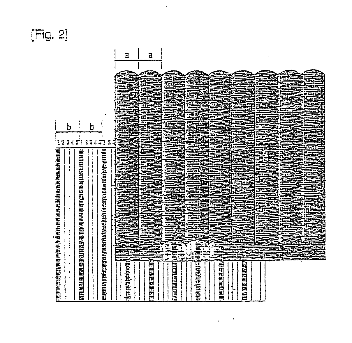
CROSS-REFERENCE TO RELATED APPLICATIONS[0001]This application is a national stage application of PCT Application No. PCT / KR2011 / 005329, filed Jul. 20, 2011, which claims the benefit of Korean Application No. 10-2010-0071695, filed Jul. 24, 2010, in the Korean Intellectual Property Office, the disclosures of which are incorporated herein by reference.BACKGROUND OF THE INVENTION[0002]1. Field of the Invention[0003]The present invention relates to a structure of a multi-viewpoint stereoscopic image display panel using an integral photography method, and more specifically, to a structure of a display panel, which can expand an effective angle of view (viewing angle) by changing an array of an interlaced (multiple division synthesis) flat image pattern and enhance sharpness of an image by removing an image jump phenomenon.[0004]2. Description of the Related Art[0005]A lenticular technique or a parallax barrier technique is mainly used as a glasses-free stereoscopic image display techniqu...

Claims


Application Information

Patent Timeline
IPC IPC(8): G02B27/22
CPCG02B27/2214G02B30/27
Inventor CHUNG, HYUNIN
Owner CHUNG HYUNIN
Learn More