
Suspended goniolens system

a goniolens and ophthalmology technology, applied in the field of mechanical equipment, can solve the problems of unsatisfactory use of a dedicated hand during surgical intervention, and inability to appropriately treat any glaucoma condition,

Inactive Publication Date: 2013-07-18
SCHARIOTH GABOR
View PDF2 Cites 45 Cited by
  • Summary
  • Abstract
  • Description
  • Claims
  • Application Information

AI Technical Summary

Benefits of technology

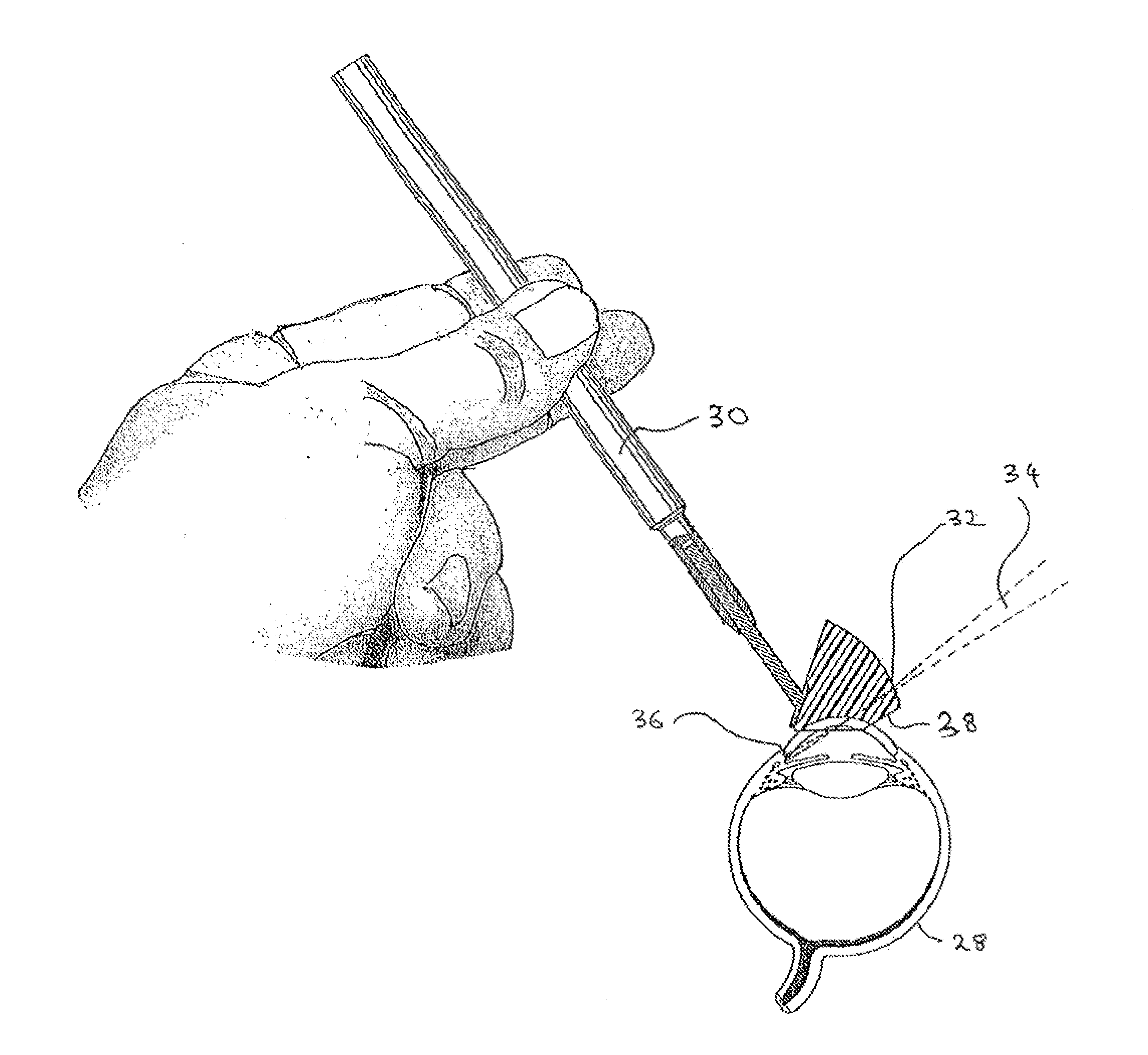
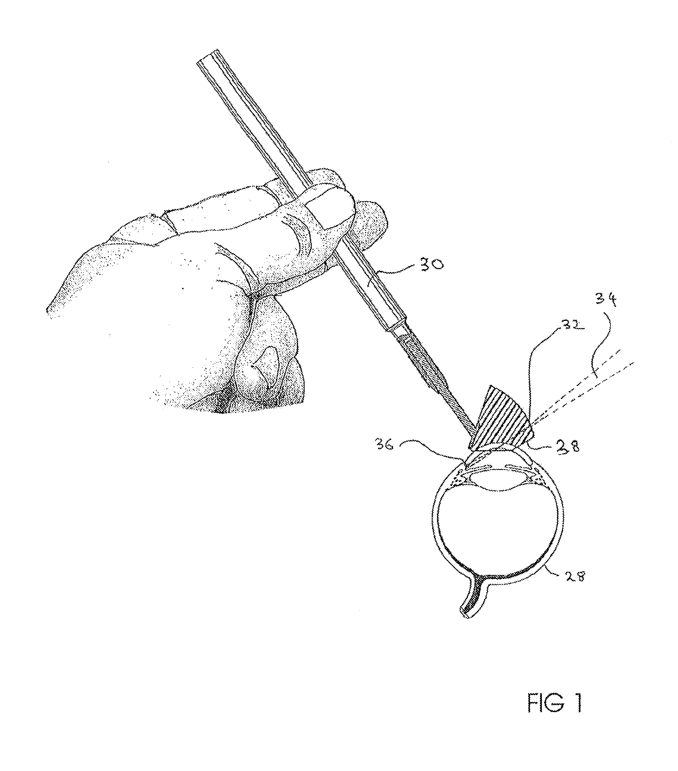
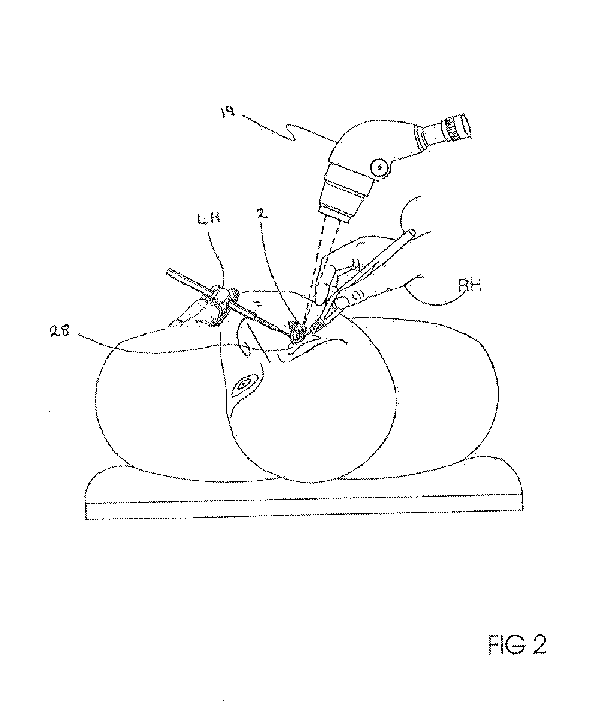
The patent describes optical systems that can be used for medical procedures on a patient's eye. The systems have a balance arm with a movable counterbalance weight and a goniolens that can be adjusted to apply force to the eye. The systems can be controlled using lateral, vertical, and rotational mechanisms. The methods include positioning the microscope over the eye and the goniolens, adjusting the counterweight to control the force on the eye, and performing the medical procedure using two hands. The optical systems improve the precision and control of the procedures.

Problems solved by technology

Without gonioscopy, identification of the underlying mechanism and, therefore, the appropriate treatment of any glaucomatous condition is impossible.
The hand held technique can be acceptable for diagnostic procedures but the use of a dedicated hand used for this purpose during surgical intervention is not ideal.

Method used


Image

  • Suspended goniolens system
  • Suspended goniolens system
  • Suspended goniolens system

Examples


example 1

[0071]A suspended goniolens system was sterilized in an autoclave. The sterilized suspended goniolens system was then attached to an optical surgical microscope. The suspended goniolens was attached to an adapter attached to the head of the optical surgical microscope. The orientation of the optical axis of the microscope was set based on the procedure to be performed on the patient. The suspended goniolens system was calibrated in a lowered configuration to position the goniolens in the optical axis of the microscope. The counterbalance weight was adjusted along the balance arm to weightlessly balance the goniolens in the optical focus of the optical surgical microscope.

[0072]After the goniolens was calibrated in the focused position the suspended goniolens was moved to a raised position and rotated away from the optical axis. The suspended goniolens was then ready for the patient.

example 2

[0073]The patient is positioned on the operating table in the desired orientation to the optical axis of the optical surgical microscope. A viscoelastic fluid is applied to the surface of the eye that is to be treated by the procedure. After the patient is in the desired position the suspended goniolens system is rotated to align it with the optical axis. The goniolens is then lowered into contact with the patient's eye. The cornea coupling weight is then slid towards the goniolens to apply a desired contact force to the patient's cornea by the goniolens. The medical procedure then begins. The clinician can use both hands during the medical procedure because the goniolens is positioned in place by the suspended goniolens system. The position of the goniolens can be moved along the patient's eye as needed. The position of the microscope head is moved using the microscope positioning controls, such as foot controls. The suspended goniolens system moves with the microscope head. The go...


PUM


Abstract

A suspended goniolens system is provided. The suspended goniolens system includes a balance arm with a goniolens disposed at one end and a counterbalance disposed towards an opposing end. The system can position the goniolens in a desired position near a patient's eye and can maintain the desired position without the need to be held in place by a clinician. The suspended goniolens system allows for the clinician to use both hands during treatment of the patient. The goniolens system can be attached to an optical microscope or an adapter engaged with the optical microscope. Methods are also provided for using the goniolens system.

Description

CROSS REFERENCE TO RELATED APPLICATIONS[0001]This application claims the benefit of priority to U.S. Provisional Application Ser. No. 61 / 587,250 filed on Jan. 17, 2012, the disclosure of which is incorporated by reference herein.INCORPORATION BY REFERENCE[0002]All publications and patent applications mentioned in this specification are herein incorporated by reference to the same extent as if each individual publication or patent application was specifically and individually indicated to be incorporated by reference.FIELD[0003]The present disclosure relates generally to a mechanical apparatus that can be used to facilitate gonioscopic surgery.BACKGROUND[0004]Gonioscopy is an ophthalmology procedure that requires the use of a goniolens in addition to an operating microscope to gain a view of the anatomical angle formed between the eye's cornea and iris.[0005]The procedure allows the clinician to view the irideocorneal angle through a mirror or prism, without which the angle is masked...

Claims


Application Information

Patent Timeline
Patent Type & Authority Applications(United States)
IPC IPC(8): A61B3/117
CPCA61B3/117
Inventor WARDLE, JOHNSCHARIOTH, GABOR
Owner SCHARIOTH GABOR
Learn More