
Idling stop device

a technology of a stop device and a stop light, which is applied in the direction of engine starters, electric control, machines/engines, etc., can solve the problems of difficult to realize satisfactory and the driver feels strange, and achieves the effect of enhancing fuel economy and drivability

Active Publication Date: 2013-07-18
SUBARU CORP
View PDF16 Cites 14 Cited by
  • Summary
  • Abstract
  • Description
  • Claims
  • Application Information

AI Technical Summary

Benefits of technology

The present invention provides an idling stop device that can set the best time to stop idling, based on the external environment, to improve fuel economy and driving performance. This device can also optimize the starting speed of the vehicle when it idles.

Problems solved by technology

If the idling stop condition is satisfied during the deceleration, the engine is uniformly stopped (idling stop), so that there is a delay in the re-acceleration, which might provide a feeling of strangeness to the driver.
In the technique described above, the idling stop condition is uniformly determined, so that the optimum idling stop timing cannot be obtained, resulting in that it is difficult to realize satisfactory fuel economy and drivability.

Method used


Image

  • Idling stop device
  • Idling stop device
  • Idling stop device

Examples


Embodiment Construction

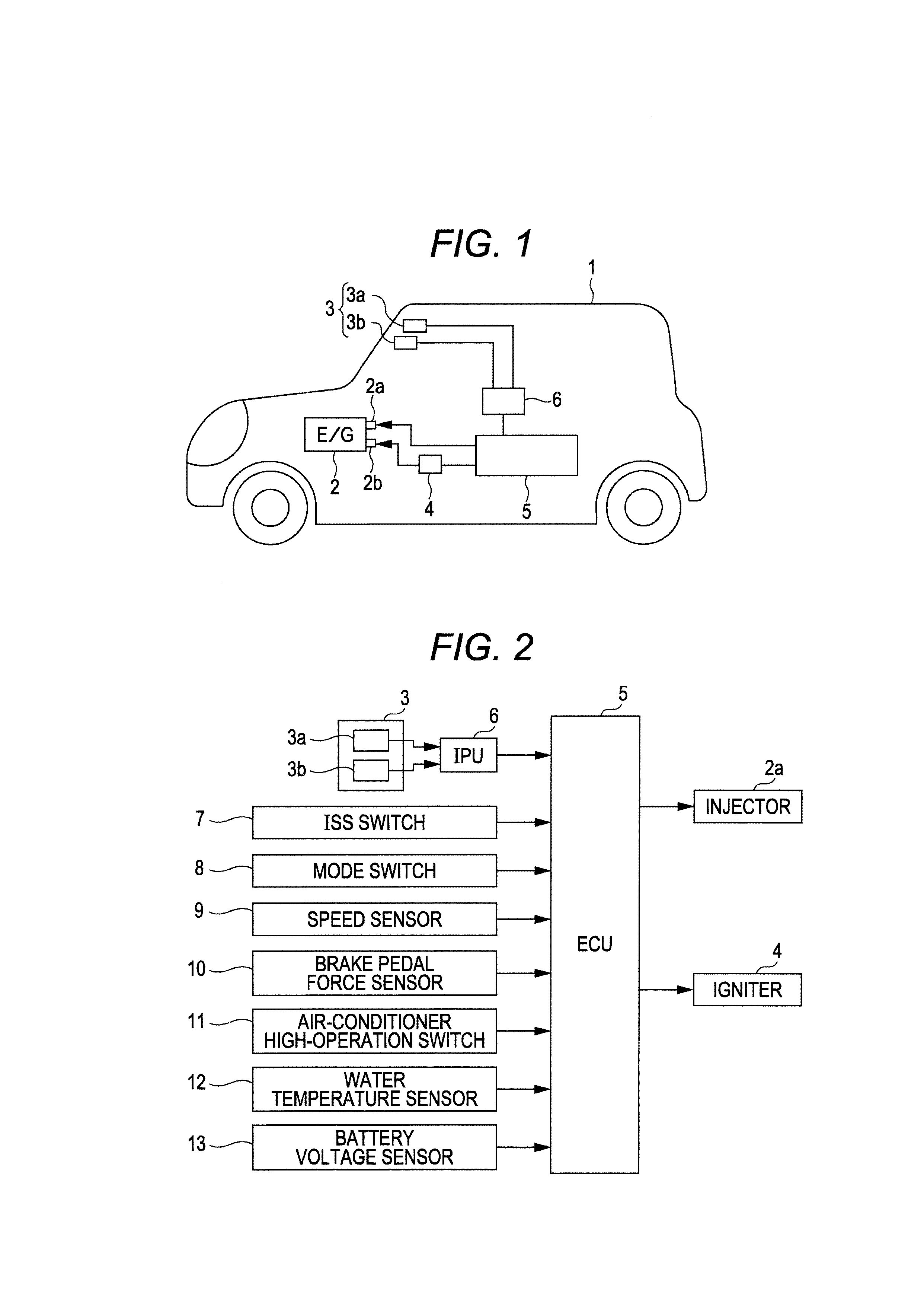
[0026]An embodiment of the present invention will be explained in detail below with reference to the drawings. A vehicle 1 in FIG. 1 is an automobile or the like and includes an engine 2 and an onboard camera 3. An injector 2a and an ignition plug 2b are mounted to each cylinder in the engine 2, and each ignition plug 2b is connected to an igniter 4.

[0027]The onboard camera 3 is one example of an external environment recognition unit. In the present embodiment, a stereo camera including a main camera 3a and a sub-camera 3b is employed. The onboard camera 3 is disposed on each side of a rearview mirror (not illustrated) on an upper central part of a front window in order to shoot environment (external environment) in front of the vehicle 1.

[0028]The vehicle 1 also has an engine control unit (ECU) 5 for controlling the engine 2. The ECU 5 outputs a fuel injection signal to the injector 2a so as to inject fuel by a predetermined calculated amount to a cylinder of interest on a predeter...


PUM


Abstract

There is provided an idling stop device. An ECU sets a lighting color index by recognizing a lighting color of a traffic light in front of a vehicle based upon external environment captured by an onboard camera, sets a distance index based upon a distance between the traffic light and a vehicle just in front of the vehicle, and sets a brake index based upon whether a brake lamp of the vehicle just in front of the vehicle is turned on or not. The ECU adds up these indices to obtain an ISS general index, sets a basic ISS speed based upon the ISS general index, and sets an ISS start speed based upon the basic ISS speed and a mode-based coefficient set based upon an engine mode.

Description

CROSS-REFERENCE TO RELATED APPLICATIONS[0001]The present application claims priority from Japanese Patent Application No. 2012-001338 filed on Jan. 6, 2012, the entire contents of which are hereby incorporated by reference.BACKGROUND OF THE INVENTION[0002]1. Field of the Invention[0003]The present invention relates to an idling stop device that sets a vehicle speed optimum for starting an idling stop based upon external environment recognized by an external environment recognition unit.[0004]2. Description of Related Art[0005]Conventionally, the idling stop device of this type stops an engine after an elapse of a predetermined time after a driver completely stops a vehicle (0 [Km / h]) in consideration of change of mind (in re-acceleration just before or just after a driver stops the vehicle).[0006]However, there has recently been known a technique of determining an idling stop condition (determining whether or not a brake pedal is depressed, and a vehicle speed is not more than a veh...

Claims


Application Information

Patent Timeline
IPC IPC(8): F02D28/00
CPCF02D28/00Y02T10/48F02N11/0837F02N2200/0801F02N2200/102F02N2200/125B60W50/082B60W30/17B60W30/18018B60W30/182B60W2510/305B60W2520/10B60W2540/12B60W2550/22B60W2550/306F02N11/0822B60W2554/4041B60W2555/60Y02T10/40
Inventor NISHINA, HIROTAKE
Owner SUBARU CORP
Learn More