
Thermal management system for battery electric vehicle

a technology of electric vehicle and thermal management system, which is applied in the direction of battery/fuel cell control arrangement, electric devices, propulsion by batteries/cells, etc., can solve the problems of electric vehicles, the range of electric vehicles is typically relatively short, and the weight and cost of battery packs used to store energy

Inactive Publication Date: 2013-07-11
MAGNA E CAR SYST OF AMERICA
View PDF18 Cites 57 Cited by
  • Summary
  • Abstract
  • Description
  • Claims
  • Application Information

AI Technical Summary

Benefits of technology

The invention is a thermal management system for electric vehicles that includes a motor circuit for cooling the motor, a cabin heating circuit for heating the cabin, and a battery circuit for managing the temperature of the battery. These circuits can communicate with each other and a single radiator can cool the fluid from all of them. The system also includes a controller that is programmed to turn off the battery circuit heater and move the battery circuit valve when the temperature sensed by the motor circuit is too high, and to turn on the battery circuit heater, operate the battery circuit pump, and move the battery circuit valve when the temperature sensed by the motor circuit is too low. This system helps to manage the temperature of the vehicle efficiently and ensures that the motor, battery, and cabin are always at the optimal temperature.

Problems solved by technology

While currently proposed and existing vehicles are advantageous in some respects over internal-combustion engine powered vehicles, there are problems that are associated with some electric vehicles.
A particular problem is that their range is typically relatively short as compared to internal combustion engine-powered vehicles.
This is particularly true for battery electric vehicles that are not equipped with range extender engines.
A reason for this limitation is the weight and cost of the battery packs used to store energy for the operation of such vehicles.

Method used


Image

  • Thermal management system for battery electric vehicle
  • Thermal management system for battery electric vehicle
  • Thermal management system for battery electric vehicle

Examples


Embodiment Construction

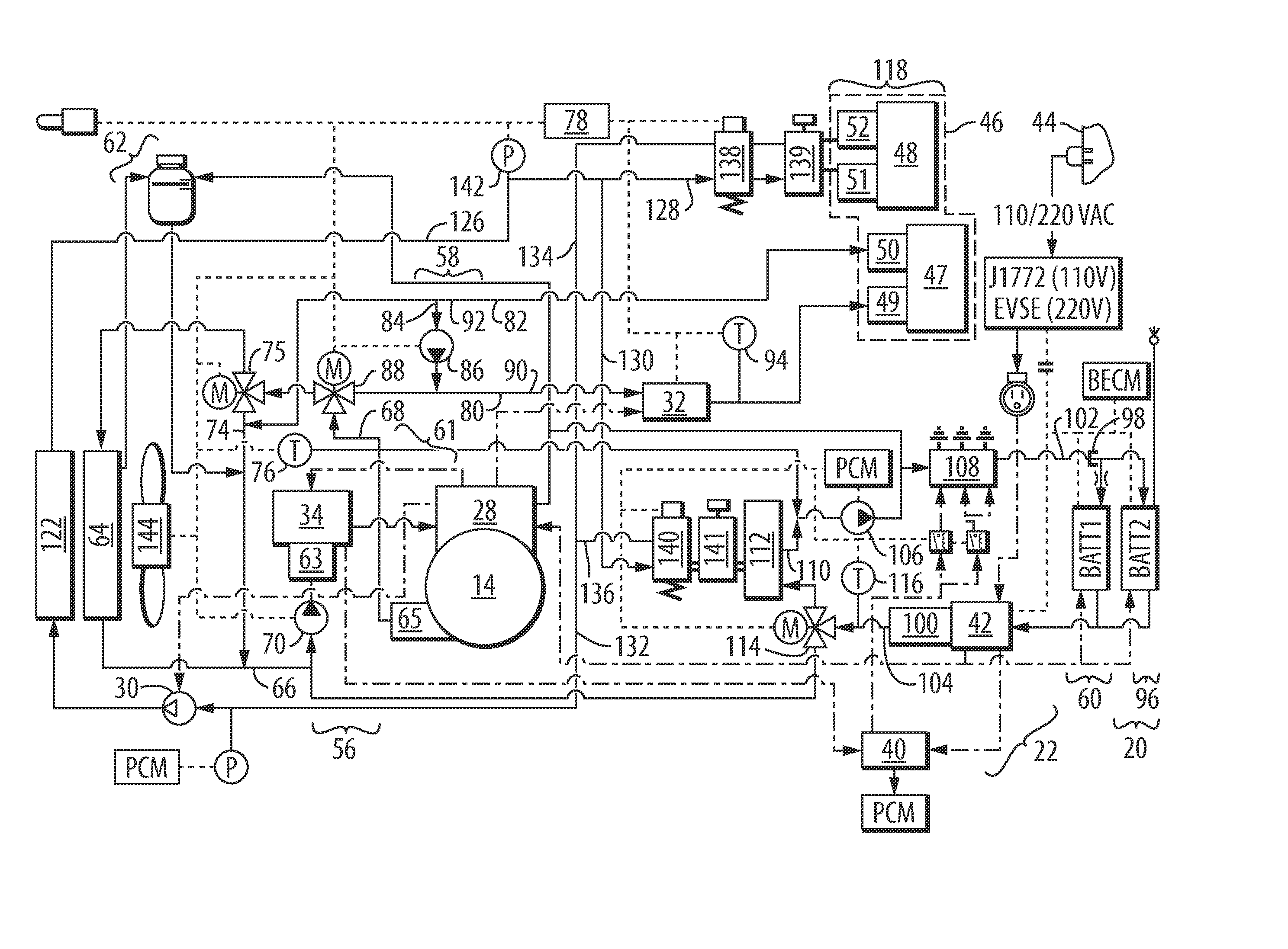
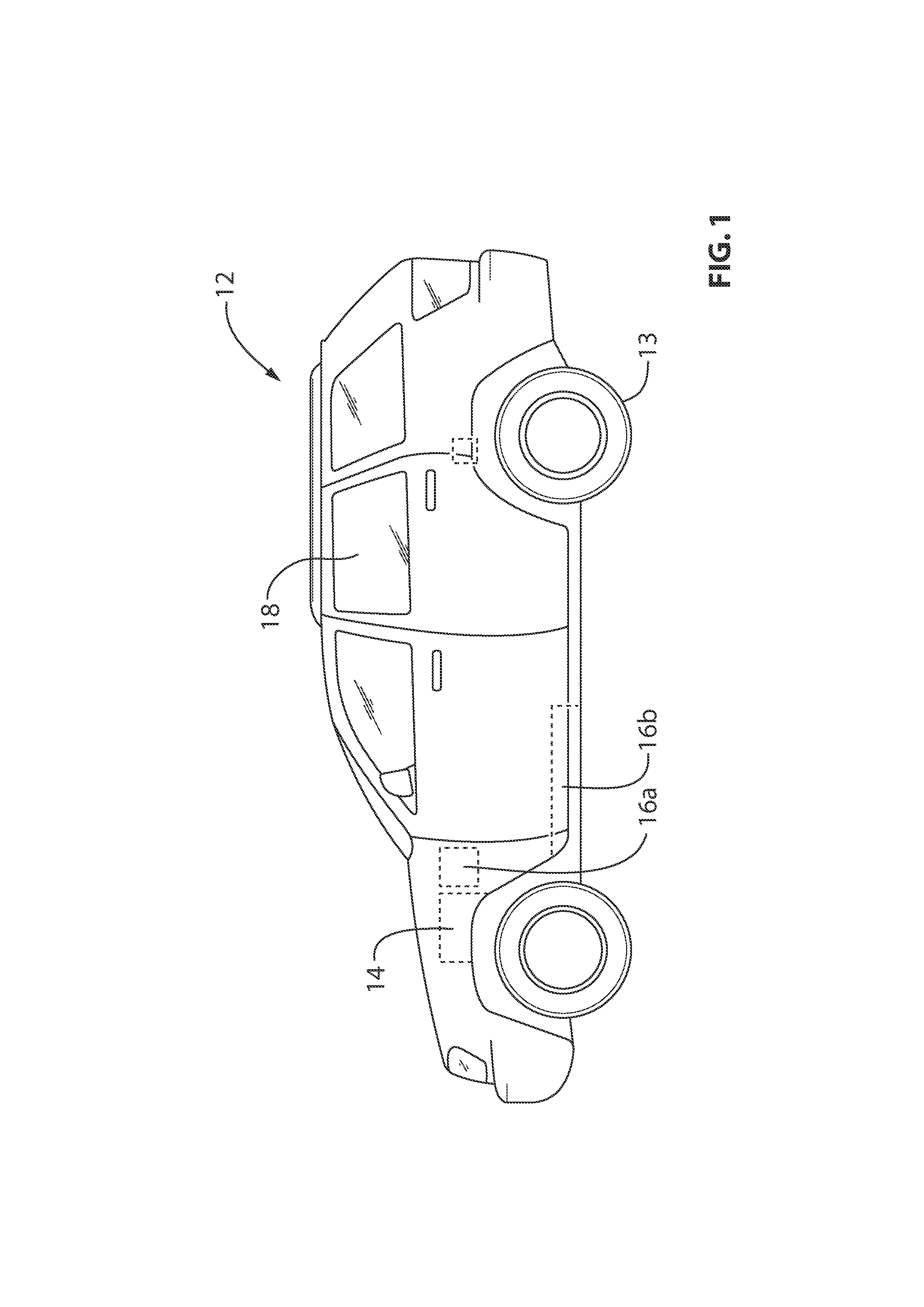
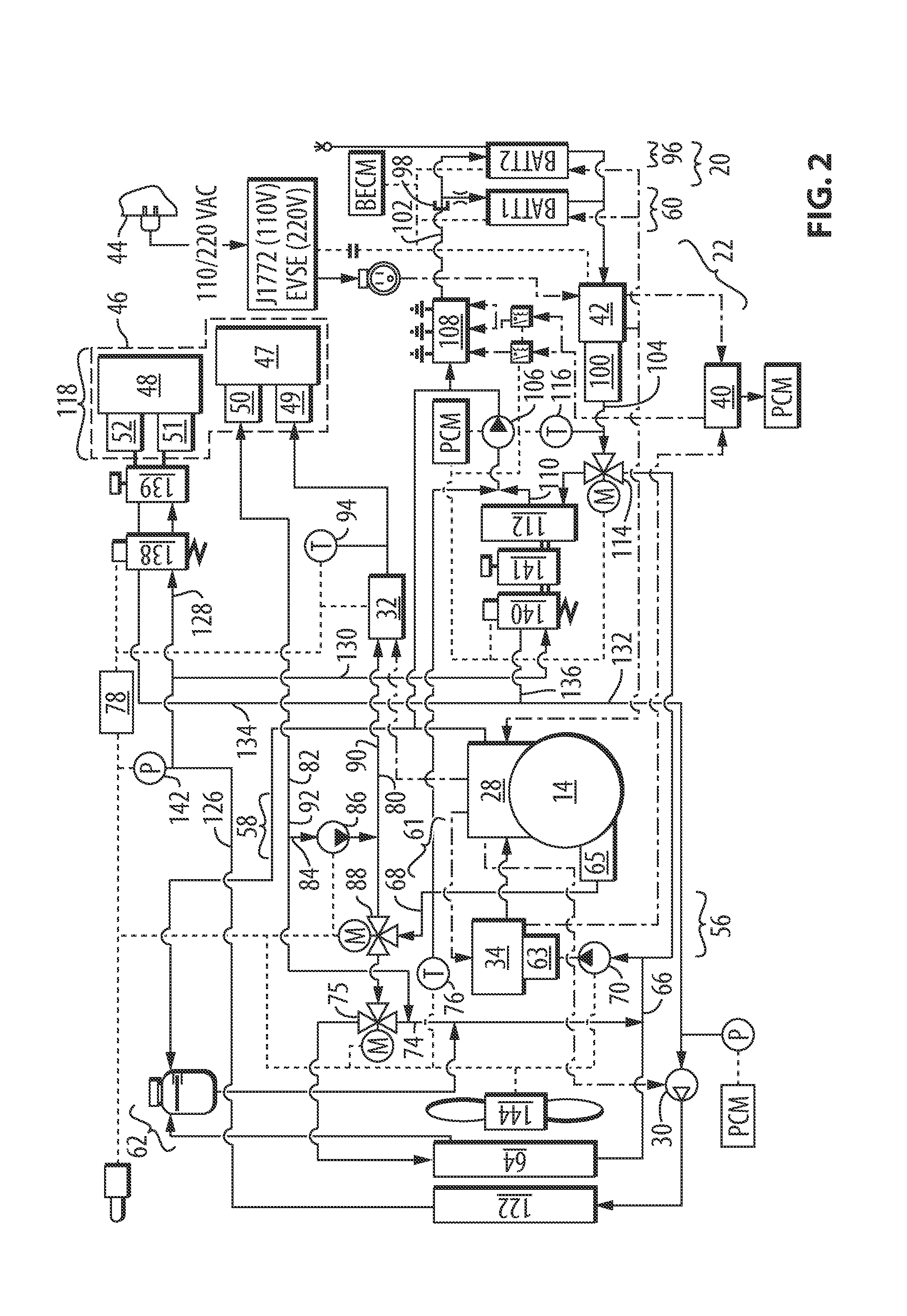
[0016]Reference is made to FIG. 2, which shows a schematic illustration of a thermal management system 10 for an electric vehicle 12 shown in FIG. 1. The electric vehicle 12 includes wheels 13, a traction motor 14 for driving the wheels 13, first and second battery packs 16a and 16b, a cabin 18, a high voltage electrical system 20 (FIG. 2) and a low voltage electrical system 22 (FIG. 2).

[0017]The motor 14 may have any suitable configuration for use in powering the electric vehicle 12. The motor 14 may be mounted in a motor compartment that is forward of the cabin 18 and that is generally in the same place an engine compartment is on a typical internal combustion powered vehicle. Referring to FIG. 2, the motor 14 generates heat during use and thus requires cooling. To this end, the motor 14 includes a motor coolant flow conduit for transporting coolant fluid about the motor 14 so as to maintain the motor within a suitable temperature range.

[0018]A transmission control system shown at...


PUM


Abstract

A thermal management system for an electric vehicle includes a motor circuit for cooling a motor circuit thermal load, a cabin heating circuit for heating a cabin heater and a battery circuit for managing the temperature of a battery circuit thermal load. All of these circuits can fluidically communicate with each other and a single radiator can cool the fluid from all of these circuits.

Description

FIELD OF THE INVENTION[0001]The present invention relates to electric vehicles (i.e., vehicles that are powered at least partly by an electric motor) and more particularly to battery electric vehicles with no internal combustion engine on board.BACKGROUND OF THE INVENTION[0002]Electric vehicles offer the promise of powered transportation through the use of electric motors while producing few or no emissions. Some electric vehicles are powered by electric motors only and rely solely on the energy stored in an on-board battery pack. Other electric vehicles are hybrids, and include an internal combustion engine, which may, for example, be used to assist the electric motor in driving the wheels (a parallel hybrid), or which may, for example, be used solely to charge the on-board battery pack, thereby extending the operating range of the vehicle (a series hybrid). In some vehicles, there is a single, centrally-positioned electric motor that powers one or more of the vehicle wheels, and i...

Claims


Application Information

Patent Timeline
Patent Type & Authority Applications(United States)
IPC IPC(8): B60H1/00B60H1/03
CPCB60H1/00392B60H1/034B60H1/00885B60H1/00278B60W2510/246B60L1/003B60L1/02B60L3/0061B60L2240/34B60L2240/425B60L2240/545Y02T90/16B60L50/62B60L58/21B60L58/26B60L58/27B60L58/18Y02T10/62Y02T10/64Y02T10/70B60L3/0046Y02T10/7072
Inventor KING, JONATHANRAJAIE, RICKDEVOGELAERE, RICHARD A.NAISH, ADAM J.
Owner MAGNA E CAR SYST OF AMERICA
Learn More