
Composite airfoil assembly

a technology of airfoil and composite blades, which is applied in the direction of waterborne vessels, climate sustainability, machines/engines, etc., can solve the problems of labor-intensive and costly manufacturing arrangements, adds cost to the component, and is not suitable for use in the field of composite blade assembly

Active Publication Date: 2013-07-04
GENERAL ELECTRIC CO
View PDF4 Cites 13 Cited by
  • Summary
  • Abstract
  • Description
  • Claims
  • Application Information

AI Technical Summary

Benefits of technology

This patent describes a composite airfoil assembly for mounting in a slot on a turbine wheel. The assembly includes a ceramic blade and a metal platform. The ceramic blade is captured within the metal platform, allowing it to be held independently in the turbine wheel. This design provides improved performance and durability. The patent also includes a method for assembling the ceramic blade to the metal platform, which involves casting the metal platform around the blade. This invention allows for the efficient use of advanced materials and designs for high-performance turbine rotors.

Problems solved by technology

This adds cost to the component due to material, labor and machining costs that are associated with the fabrication of the integrated platform system.
In fact, these are rather large costs in the overall cost distribution of the part manufacture.
These arrangements are also labor- intensive and costly to manufacture.

Method used


Image

  • Composite airfoil assembly
  • Composite airfoil assembly
  • Composite airfoil assembly

Examples


Embodiment Construction

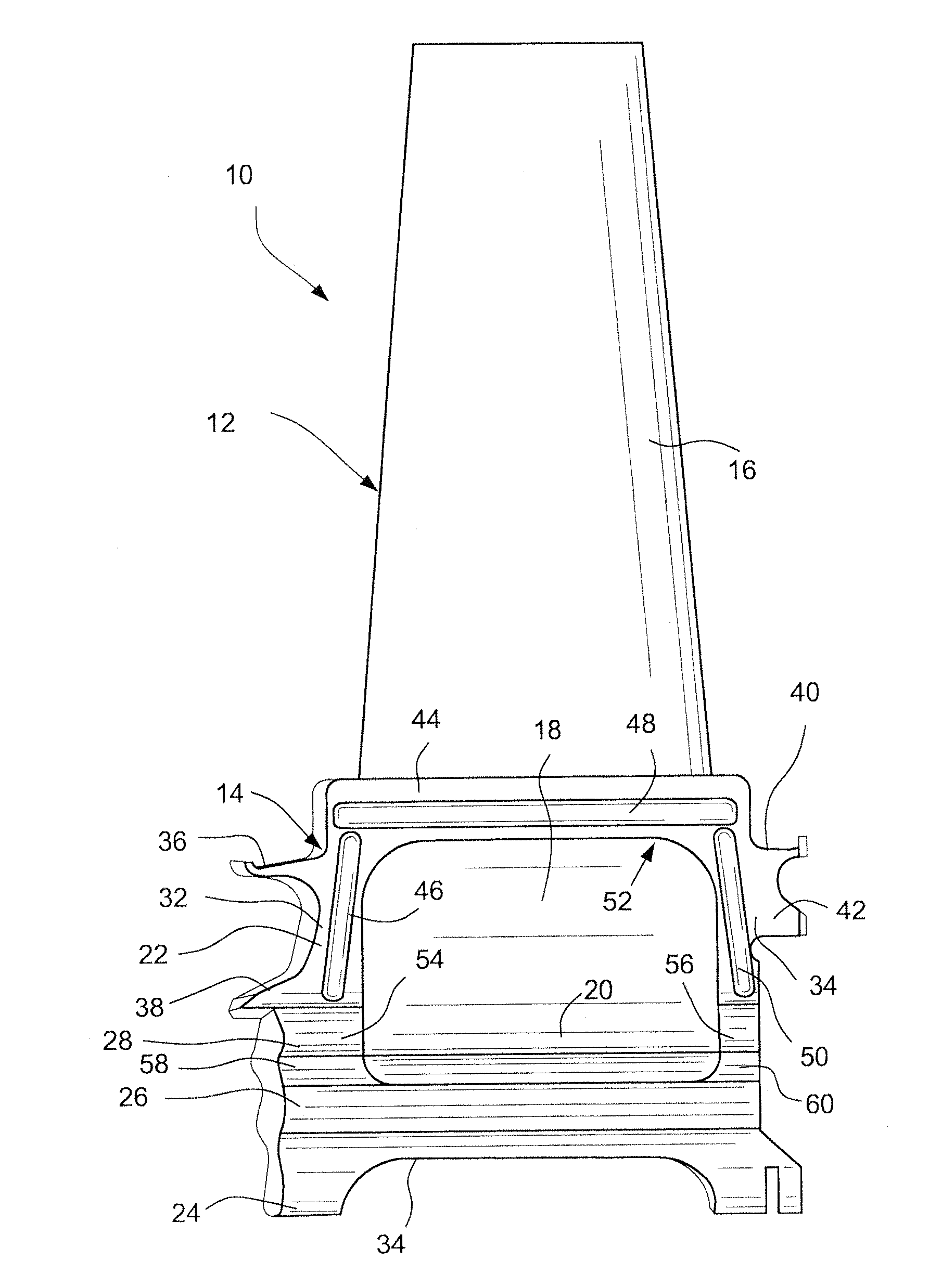
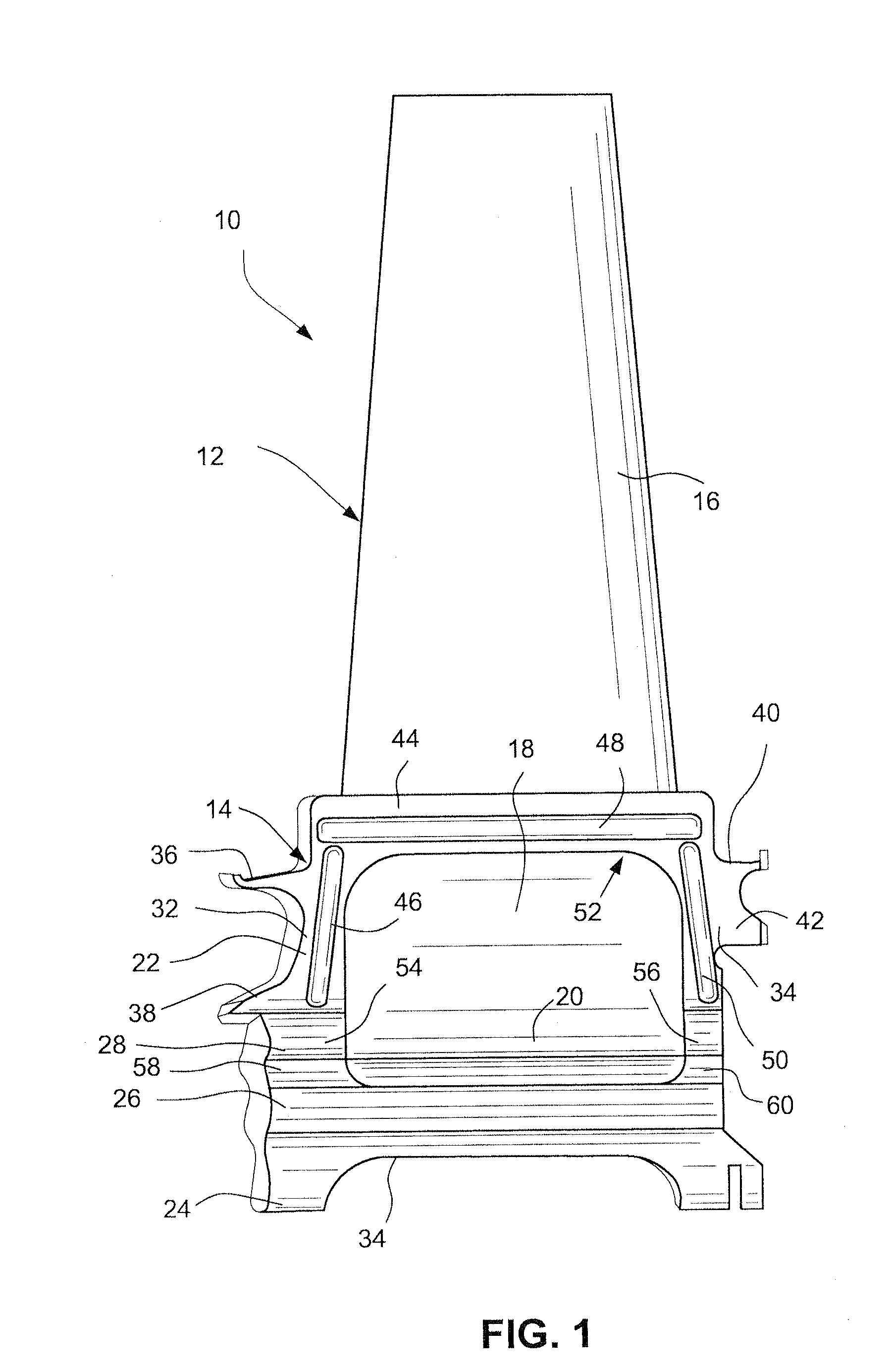
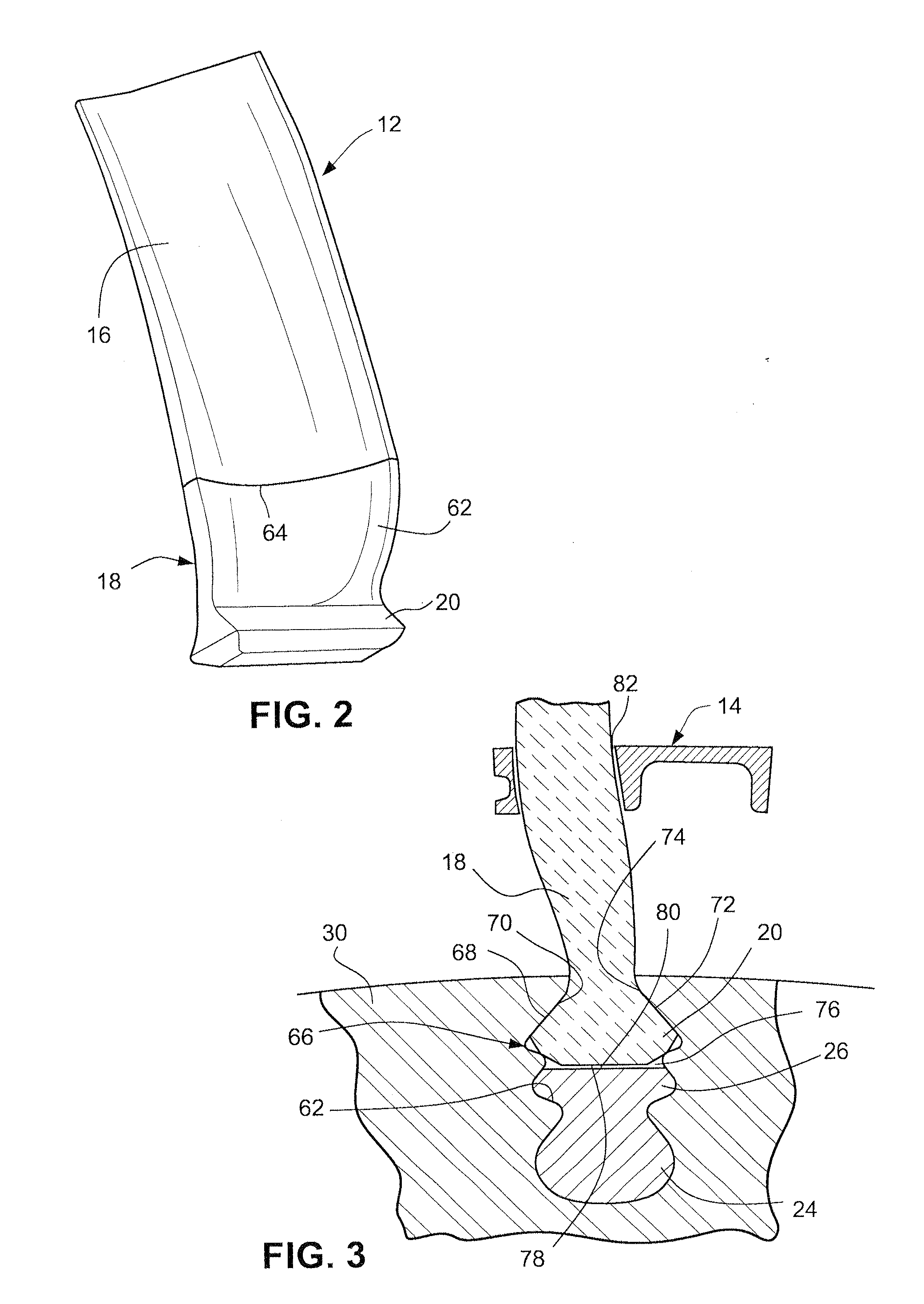
[0015]With reference initially to FIGS. 1-3, a composite blade assembly 10 in accordance with an exemplary but nonlimiting embodiment of the invention includes a ceramic airfoil 12 and a metal platform 14. As best seen in FIG. 2, the ceramic airfoil 12 includes an airfoil portion 16 a shank portion 18 and a dovetail tang 20 at its radially innermost end.

[0016]The metal platform 14 (FIG. 1) includes a platform shank 22 and oppositely-extending and otherwise conventional platform dovetail tangs 24, 26 and 28 that are adapted to be received in a mating slot formed in a rotor wheel 30 (see FIG. 3) as described further herein. The platform shank 22 includes opposite shank ends 32, 34 provided with angel wing seals 36, 38 on one end, and seals 40, 42 on the opposite end. One or both of the so-called “slash faces” (one shown at 44) may be formed with elongated grooves 46, 48, 50 to allow placement of axial and / or radial pin seals (not shown), if required. The metal platform 14 is thus seen...


PUM


Abstract

A composite blade assembly for mounting on a turbine wheel includes a ceramic airfoil and an airfoil platform. The ceramic airfoil is formed with an airfoil portion, a blade shank portion and a blade dovetail tang. The metal platform includes a platform shank and a radially inner platform dovetail. The ceramic airfoil is captured within the metal platform, such that in use, the ceramic airfoil is held within the turbine wheel independent of the metal platform.

Description

GOVERNMENT SUPPORT CLAUSE[0001]This invention was made with Government support under Contract No. DE-FC26-05NT42643 awarded by the Department of Energy. Accordingly, the Government has certain rights in the invention.BACKGROUND OF THE INVENTION[0002]This invention relates to a composite blade assembly for use in turbomachinery, and particularly to an interface between a ceramic airfoil and a metal platform.[0003]Current practice relating to ceramic blade configurations requires integral platform sections that are incorporated at the base of the airfoil during the manufacturing process. This adds cost to the component due to material, labor and machining costs that are associated with the fabrication of the integrated platform system. In fact, these are rather large costs in the overall cost distribution of the part manufacture.[0004]Other composite blades include separately-formed airfoils and platforms, attached by mechanical means on the rotor. Still other composite blades use che...

Claims


Application Information

Patent Timeline
IPC IPC(8): F01D5/14B23P15/04
CPCF01D5/147F01D5/284F01D5/3007Y10T29/49321F01D11/008F05D2300/6033F01D5/3084Y02T50/60Y10T29/4932Y10T29/49337
Inventor GARCIA-CRESPO, ANDRES JOSE
Owner GENERAL ELECTRIC CO
Learn More