Media conveyance device and printing device

a technology of media conveyancing and printing device, which is applied in the direction of printing, thin material processing, printing apparatus, etc., can solve the problems of paper buckles and curves between paper feeds, paper may be wrinkled, and it may not be possible to reliably push the print medium against the guide, etc., to achieve low cost, reduce frictional resistance of the surface that contacts the print medium, and great frictional resistance with the print medium

Active Publication Date: 2013-07-04
SEIKO EPSON CORP
View PDF38 Cites 1 Cited by
  • Summary
  • Abstract
  • Description
  • Claims
  • Application Information

AI Technical Summary

Benefits of technology

[0017]Because the first roller that rotates in the conveyance direction of the print medium urges the print medium in a direction crosswise to the conveyance direction causing an edge of the print medium to contact the guide, reliably pushing the print medium against the guide may not be possible if the frictional resistance with the print medium is great. By making the first roller from polyacetal (POM: polyoxymethylene), the frictional resistance of the surface that contacts the print medium can be reduced, and a low cost first roller that is easy to mold and has sufficient strength for use as a structural member can be achieved.
[0018]The second roller is also disposed with the axis of rotation intersecting the conveyance direction of the print medium, and the print medium slides against the second roller. Because the coefficient of friction can be reduced by making the second roller from stainless steel, the print medium slides easily. A second roller that is worn very little by the sliding print medium and is resistant to corrosion can therefore be achieved.

Problems solved by technology

However, if roll paper is used as the print medium and paper skew produced near the paper feed unit is corrected by providing a conveyance roller pair directly before the recording unit as described in JP-A-2007-84227, the paper may buckle and curve between the paper feed unit and the conveyance roller pair, and the paper may be wrinkled when supplied to the recording unit.
Because the first roller that rotates in the conveyance direction of the print medium urges the print medium in a direction crosswise to the conveyance direction causing an edge of the print medium to contact the guide, reliably pushing the print medium against the guide may not be possible if the frictional resistance with the print medium is great.

Method used


Image

  • Media conveyance device and printing device
  • Media conveyance device and printing device
  • Media conveyance device and printing device

Examples


embodiment 1

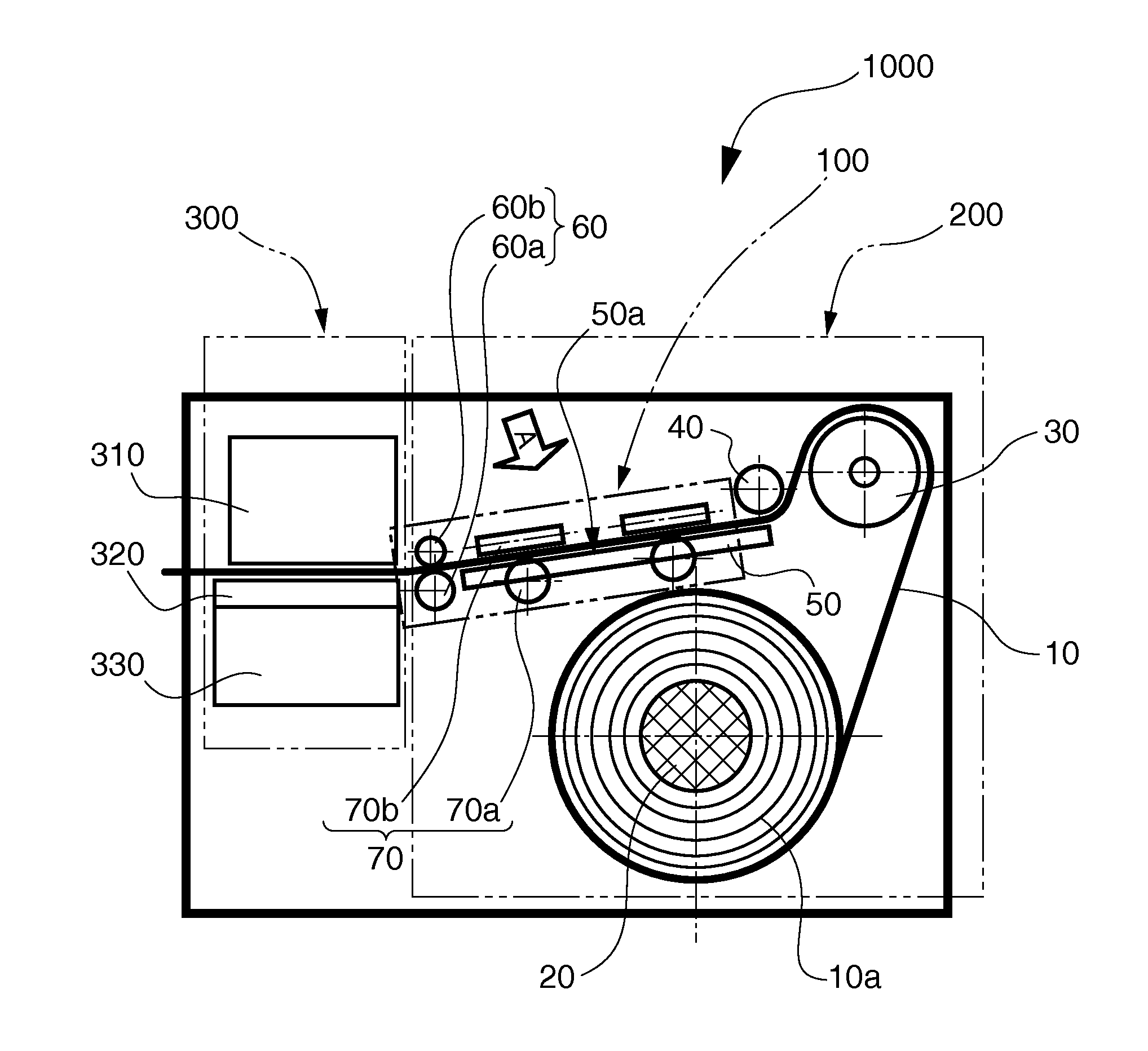
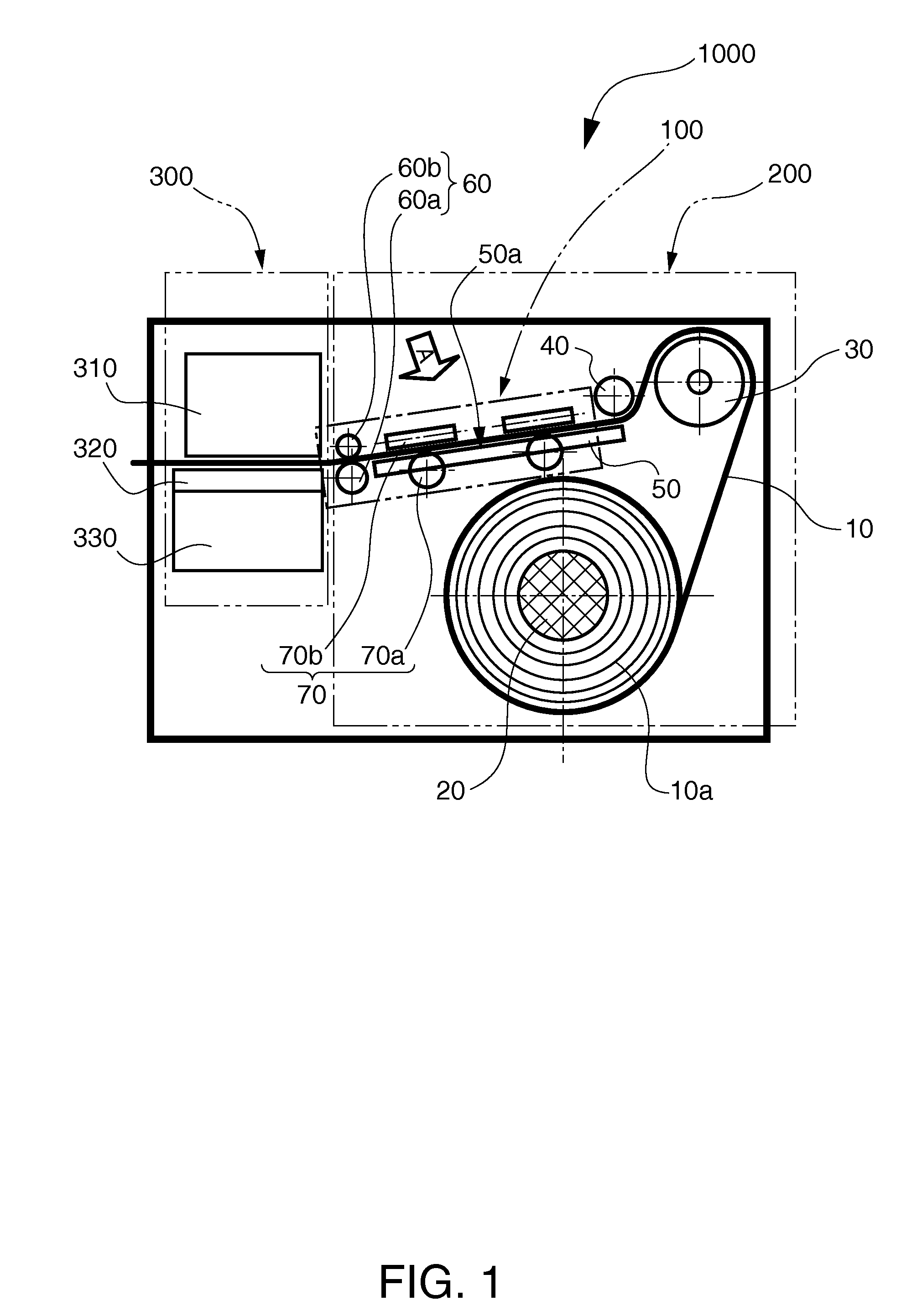
[0034]FIG. 1 is a section view showing the configuration of a printing device having a conveyance unit according to a preferred embodiment of the invention. As shown in FIG. 1, the printing device 1000 according to this embodiment has a paper feed unit 200 that stores and supplies recording paper 10 as the print medium to the recording means, and a print unit 300 as a recording means that records specific images to the supplied recording paper 10. The print unit 300 includes a recording unit 310 with an inkjet head, for example, disposed to the recording surface side of the recording paper 10, and a suction mechanism 330 and recording paper suction unit 320 that apply suction to the opposite side of the recording paper 10 as the recording surface to hold the recording paper 10 for recording.

[0035]The recording paper 10 is delivered from roll paper 10a stored in a roll in the paper feed unit 200. The roll paper 10a is installed to a roll paper drive shaft 20 that is disposed rotatabl...

embodiment 2

[0061]FIG. 4 shows a conveyance unit 110 as an example of a conveyance device according to a second embodiment of the invention. This conveyance unit 110 differs from the conveyance unit 100 of the first embodiment by using an urging unit 90 as an urging means that urges the recording paper 10 to the guide 80. Other aspects are the same as in the conveyance unit 100, identified by like reference numerals, and further description thereof is omitted.

[0062]As shown in FIG. 4, the urging unit 90 of the conveyance unit 110 according to the second embodiment of the invention has an urging end 91 with a face 91a that contacts the opposite edge 10c of the recording paper 10 as the edge 10b that contacts the guide 80, and a coil spring 92 as an urging member that urges the urging end 91 towards the guide 80.

[0063]The urging unit 90 is disposed to the recording paper support unit 50 movably relative to the width Wp of the recording paper 10 by a position adjusting means not shown, and applies...


PUM


Abstract

A printing device has a guide roller that guides a print medium in a conveyance direction; an intersect roller pair that holds the print medium guided by the guide roller between a first roller that rotates on an axis of rotation in the conveyance direction of the print medium and a second roller that rotates on an axis of rotation that intersects the axis of rotation of the first roller; a conveyance roller pair that conveys the print medium held by the intersect roller pair in the conveyance direction by a conveyance drive roller driven by a drive means and a conveyance follower roller that rotates with the conveyance drive roller; and a print unit that prints on the print medium conveyed by the conveyance roller pair.

Description

BACKGROUND[0001]1. Technical Field[0002]The present invention relates to a media conveyance device and to a printing device.[0003]2. Related Art[0004]Conveyance roller pairs used to convey paper as the recording medium to the recording unit in a recording device typically include a conveyance drive roller that is driven by a drive motor, and a conveyance follower roller that follows the rotation of the conveyance drive roller. In order for the conveyance roller pair to convey the paper to the recording unit straight, the rotational axes of the conveyance drive roller and follower roller are disposed perpendicularly to the conveyance direction as described in Japanese Unexamined Patent Appl. Pub. JP-A-2002-265089.[0005]The paper may also become skewed to the conveyance direction while being conveyed. There are various reasons for this, including frictional resistance from the edge of the conveyed paper sliding against part of the conveyance path, and conveyance starting with the pape...

Claims


Application Information

Patent Timeline
Patent Type & Authority Applications(United States)
IPC IPC(8): B41J13/02
CPCB41J13/02B41J15/04B41J13/025
Inventor HAMAKAWA, HIROSHIISHIDA, TETSUGO
Owner SEIKO EPSON CORP
Why Eureka
Try Eureka