
Method for measuring an electrical current and apparatus for this purpose

Active Publication Date: 2013-07-04
MAGNA STEYR FAHRZEUGTECHN
View PDF8 Cites 9 Cited by
  • Summary
  • Abstract
  • Description
  • Claims
  • Application Information

AI Technical Summary

Benefits of technology

The patent text describes a method for accurately measuring various parameters of a specific transistor, such as drain-source current, drain-source voltage, and gate-source voltage. The method involves determining the relationship between these parameters during an initialization step, rather than relying on manufacturer data sheets. This helps to account for any changes in these parameters that may occur due to manufacturing tolerances or aging. Additionally, the method takes advantage of using a temperature sensor that is located on the same substrate as the transistor to minimize errors in measuring temperature. Overall, this method provides a more accurate and reliable way to characterize the performance of transistors.

Problems solved by technology

A disadvantage of the known methods is that it is only possible to measure currents with a relatively small range of values.
The known circuits are thus unsuitable for larger ranges of measurement, or must be extended using complicated circuits to expand the range of measurement.

Method used


Image

  • Method for measuring an electrical current and apparatus for this purpose
  • Method for measuring an electrical current and apparatus for this purpose
  • Method for measuring an electrical current and apparatus for this purpose

Examples


Embodiment Construction

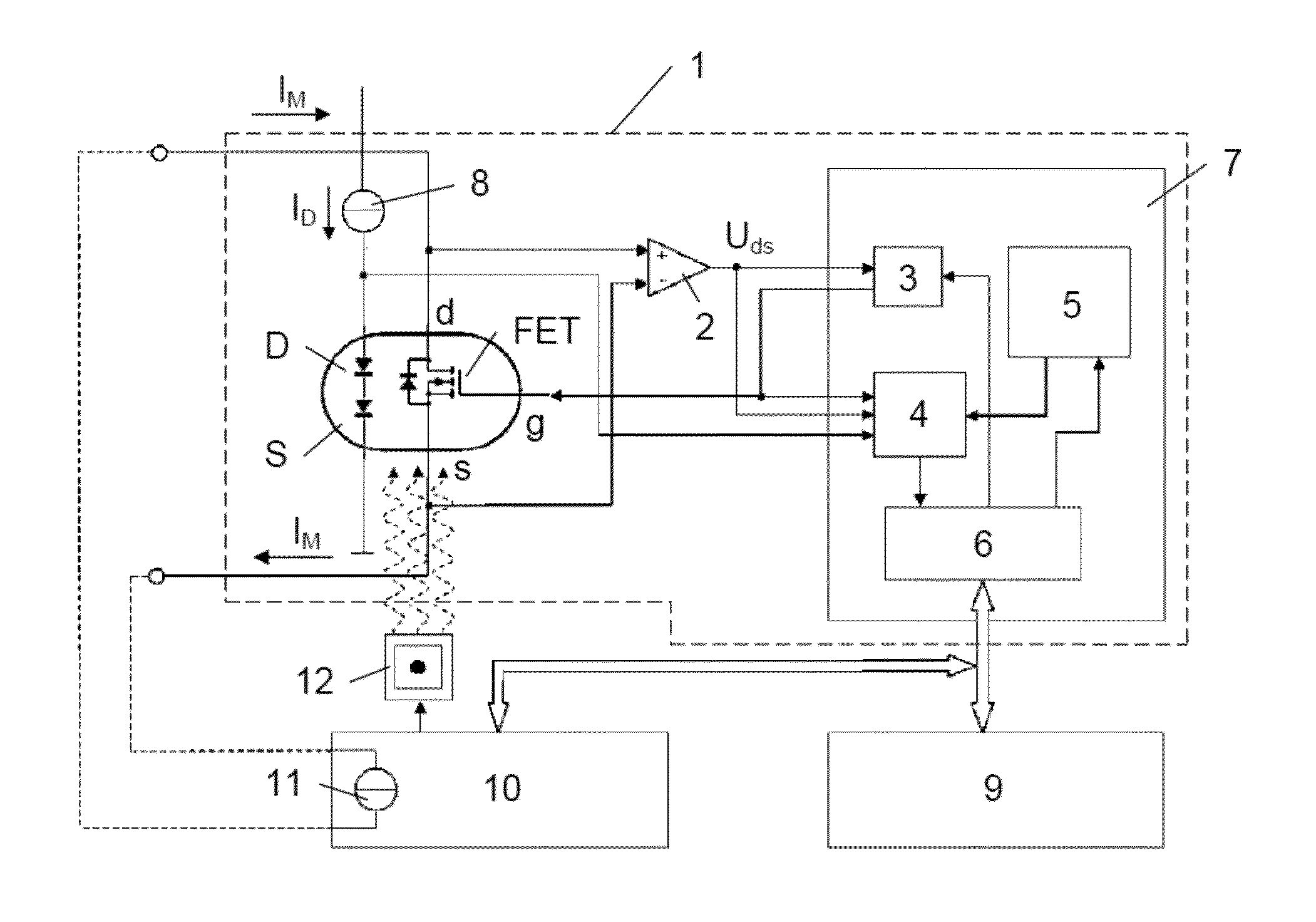
[0046]FIG. 5 illustrates a variant of apparatus 1 in accordance with the invention for measuring a current IM. The apparatus 1 comprises a transistor FET that is connected by its drain d and source s in a current path. A differential amplifier 2 measures the drain-source voltage Uds and supplies it to a control unit 3. The drain-source voltage Uds is also fed to an input of a measurement acquisition unit 4. An output of the control unit 3 is connected to the gate g of the transistor FET and to an input of the measurement acquisition unit 4. Finally, the measurement acquisition unit 4 is connected to a memory 5, in which the relationship between the drain-source current Ids, the drain-source voltage Uds and the gate-source voltage Ugs is stored, for instance in the form of a function for the drain-source current Ids as a function of the drain-source voltage Uds and of the gate-source voltage Ugs. The apparatus 1 also comprises a data interface 6 for communication of the control unit ...


PUM


Abstract

A method for measuring an electrical current with the aid of a field effect transistor inserted into a current path and an apparatus for implementing the method. A control voltage is applied between the gate and source of the transistor in such a way that the voltage drop between the drain and source at the transistor in the current path remains within a specifiable range. The voltage drop and the control voltage are determined. With these two values, and with a known relationship between the drain-source current, the drain-source voltage and the gate-source voltage the value of the current of interest can now be determined.

Description

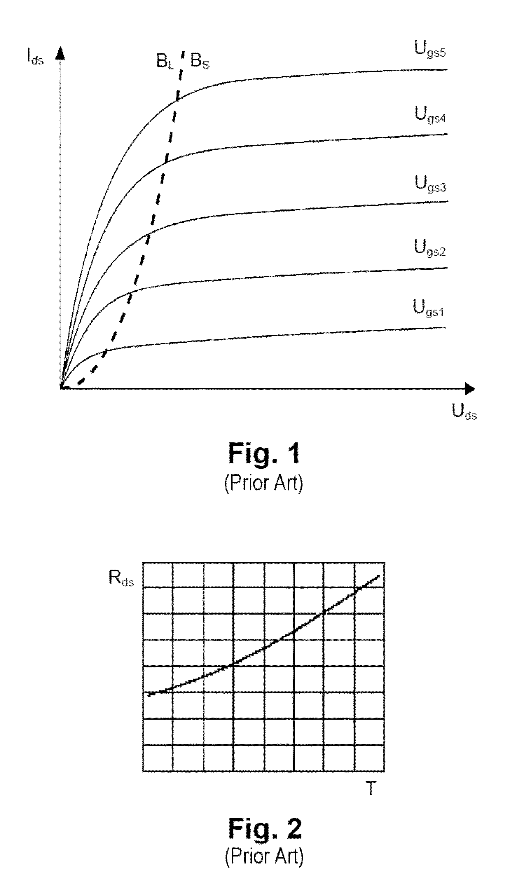
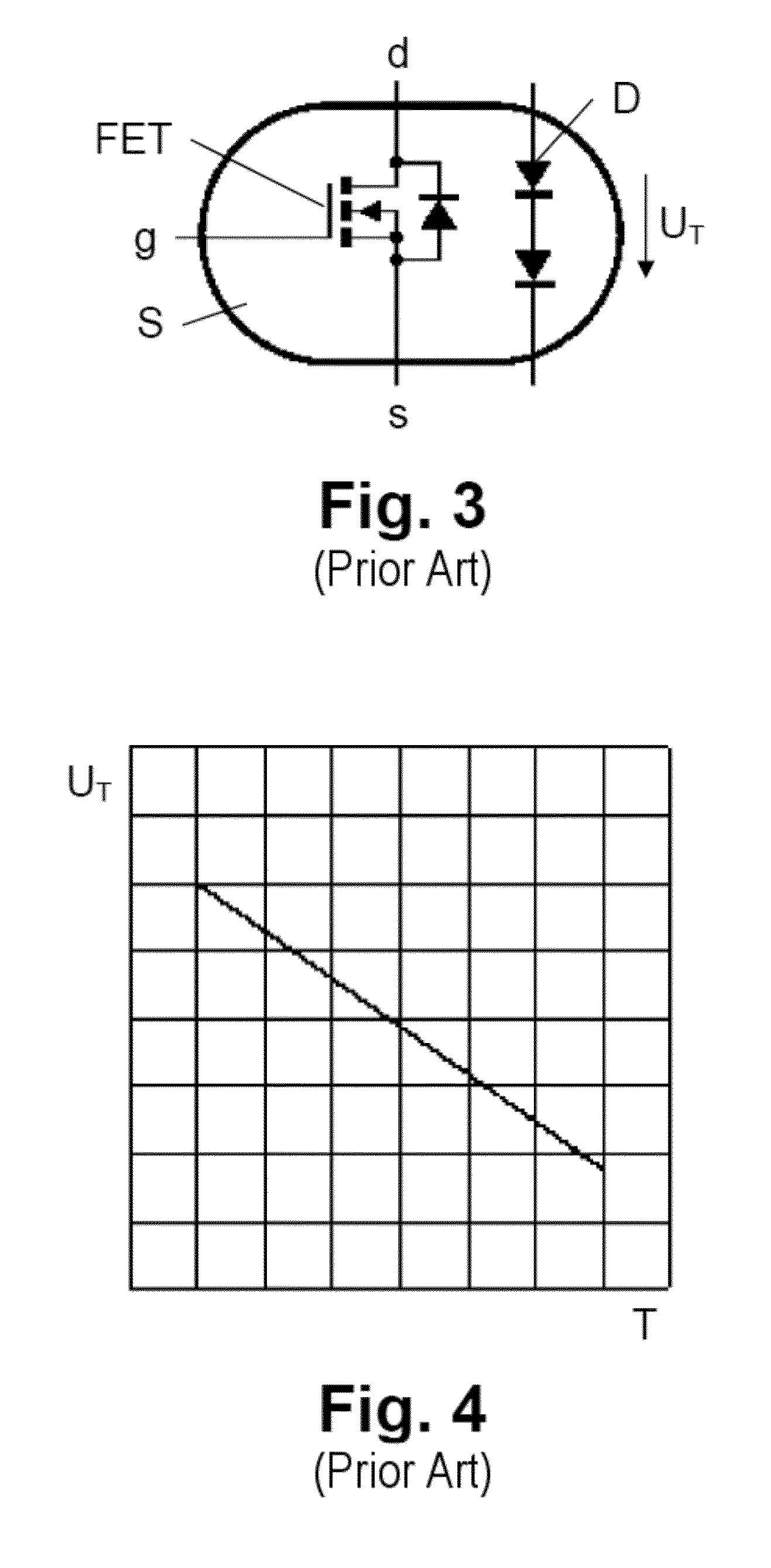
CROSS-REFERENCE TO RELATED APPLICATIONS[0001]The present application is a National Stage Application of PCT International Application No. PCT / EP2011 / 054151 (filed on Mar. 18, 2011), under 35 U.S.C. §371, which claims priority to German Patent Application No. 10 2010 012 101.0 (filed on Mar. 19, 2010) German Patent Application No. 10 2010 011 869.9 (filed on Mar. 18, 2010), which are each hereby incorporated by reference in their respective entireties.FIELD OF THE INVENTION[0002]The invention relates to a method for measuring an electrical current with the aid of a field effect transistor inserted into a current path, in which a voltage drop between the drain and source at the transistor in the current path is measured, and the value of the current of interest is determined on the basis of the voltage drop and of a known relationship between the drain-source current and the drain-source voltage.[0003]The invention furthermore relates to apparatus for measuring an electrical current, ...

Claims


Application Information

Patent Timeline
IPC IPC(8): G01R19/00
CPCG01R19/00G01R19/0092G01R19/16519G01R27/26G01R27/08G01R27/02G01R27/16G01R27/14
Inventor PILZ, KARL
Owner MAGNA STEYR FAHRZEUGTECHN
Learn More