
Arrangement for introducing a liquid medium into exhaust gases from a combustion engine

a technology of combustion engine and liquid medium, which is applied in the direction of machines/engines, mechanical equipment, transportation and packaging, etc., can solve problems such as turbulence of flow

Inactive Publication Date: 2013-07-04
SCANIA CV AB
View PDF3 Cites 38 Cited by
  • Summary
  • Abstract
  • Description
  • Claims
  • Application Information

AI Technical Summary

Benefits of technology

The invention is about a system for reducing the formation of lumps and drops of liquid in an exhaust gas stream. The system includes a mixing duct with two exhaust vortices that rotate in opposite directions, creating a turbulent flow that prevents the liquid from reaching the duct's walls and spreading it out in the exhaust gases. The system also includes a casing that prevents the liquid from reaching the duct's walls and a third flow guide that creates a third exhaust vortex in the mixing duct. These features work together to break up the liquid drops and prevent them from causing problems in the exhaust system.

Problems solved by technology

The fact that the first exhaust vortex and the second exhaust vortex rotate in opposite directions results in very turbulent flow where they come into contact with one another.

Method used


Image

  • Arrangement for introducing a liquid medium into exhaust gases from a combustion engine
  • Arrangement for introducing a liquid medium into exhaust gases from a combustion engine
  • Arrangement for introducing a liquid medium into exhaust gases from a combustion engine

Examples


Embodiment Construction

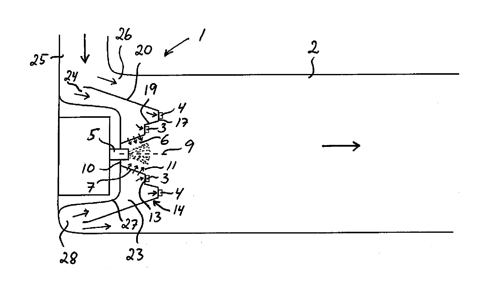
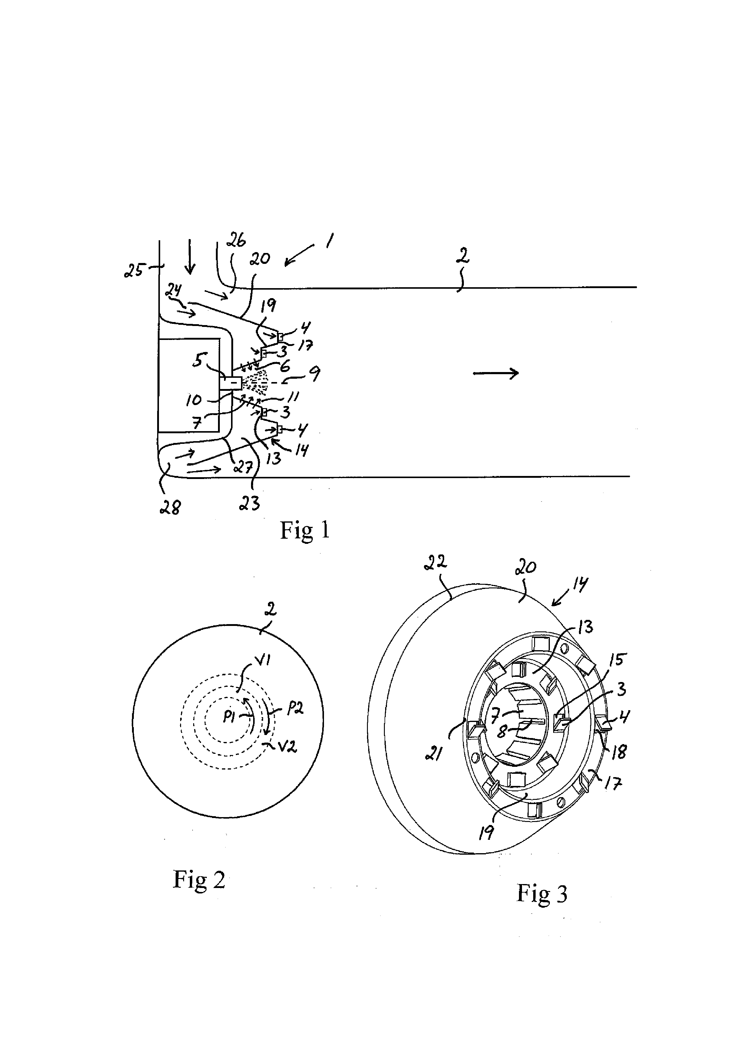
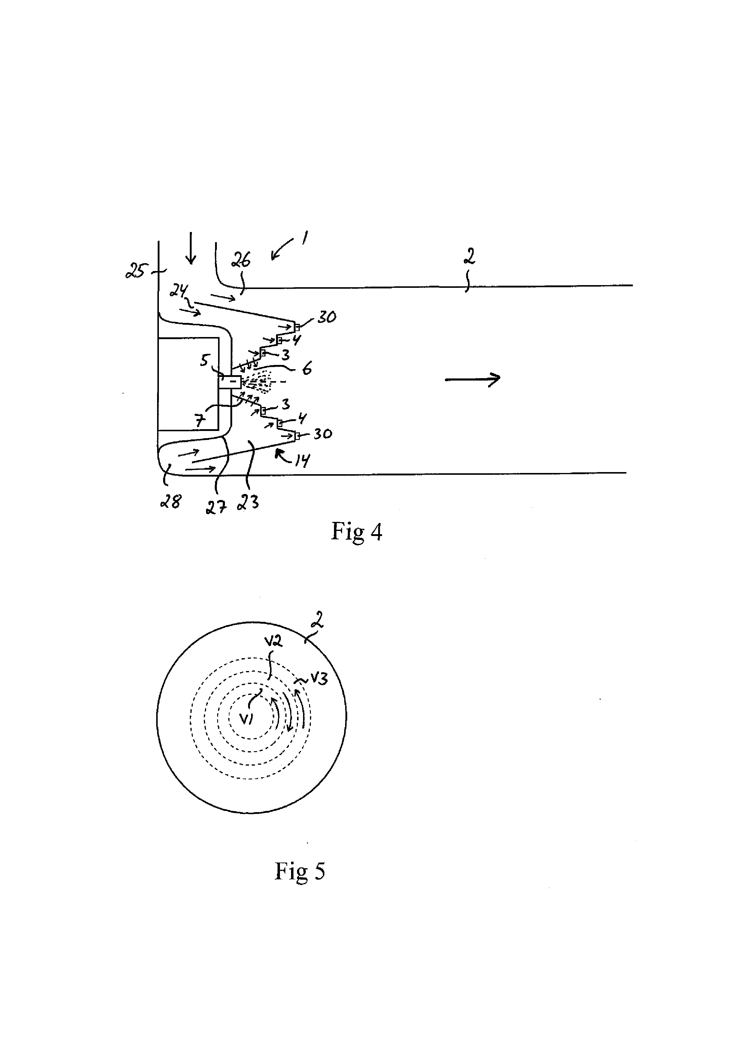
[0029]FIGS. 1 and 4 illustrate two different embodiments an arrangement 1 for introducing a liquid medium into exhaust gases from a combustion engine. The arrangement may for example be situated in an exhaust line upstream of an SCR catalyst in order to introduce a liquid reducing agent in the form of urea or ammonia into the exhaust line upstream of the SCR catalyst, or be situated in an exhaust post-treatment device in order to introduce a liquid reducing agent in the form of urea or ammonia upstream of an SCR catalyst which forms part of the exhaust post-treatment device.

[0030]The arrangement 1 comprises a mixing duct 2 intended to receive at its upstream end exhaust gases from a combustion engine and to lead them towards an exhaust post-treatment unit, e.g. in the form of an SCR catalyst. The mixing duct 2 is thus intended to have exhaust gases flowing through it.

[0031]The arrangement 1 further comprises a first flow guide 3 for creating a first exhaust vortex V1 (see FIGS. 2 an...


PUM


Abstract

Arrangement for introducing a liquid medium into exhaust gases from a combustion engine, comprising a mixing duct, a first flow guide for creating a first exhaust vortex in the mixing duct such that the exhaust gases in this first exhaust vortex rotate in a first direction of rotation during their movement downstream in the mixing duct, an injector for injecting the liquid medium in the form of a finely divided spray into exhaust gases which are led into the liquid medium in an exhaust flow at the centre of the first vortex, and a second flow guide for creating a second exhaust vortex in the mixing duct concentrically with and externally about the first vortex, such that the exhaust gases in this second vortex rotate in a second direction of rotation, which is opposite to said first direction of rotation, during their movement downstream in the mixing duct.

Description

[0001]The present application is a 35 U.S.C. §§371 national phase conversion of PCT / SE2011 / 051178, filed Oct. 4, 2011, which claims priority of Swedish Application No. 1051048-5, filed Oct. 6, 2010, the contents of which are incorporated by reference herein. The PCT International Application was published in the English language.BACKGROUND OF THE INVENTION[0002]1. Field of the Invention[0003]The present invention relates to an arrangement for introducing a liquid medium, e.g. urea, into exhaust gases from a combustion engine.[0004]2. Related Art[0005]To meet prevailing exhaust cleaning requirements, today's motor vehicles are usually provided with a catalyst in the exhaust line to effect catalytic conversion of environmentally hazardous constituents of the exhaust gases to environmentally less hazardous substances. A method which has been employed for achieving effective catalytic conversion is based on injecting a reducing agent into the exhaust gases upstream of the catalyst. A re...

Claims


Application Information

Patent Timeline
IPC IPC(8): F01N3/10
CPCF01N3/2066F01N3/2892F01N2240/20F01N2610/02F01N3/10B01F5/0062B01F5/0451B01F3/04049F01N2610/1453B01F23/2132B01F25/102B01F2025/931B01F25/3131F01N3/20F01N3/24F01N3/206
Inventor LOMAN, PETER
Owner SCANIA CV AB
Learn More