
Expandable retrograde drill

a retrograde drill and expandable technology, applied in the field of surgical reamers or orthopedic drilling instruments, can solve the problems of increasing the duration of surgical procedures, and increasing the risk of unintended injury or consequences to patients, so as to achieve efficient and minimally invasive effects

Inactive Publication Date: 2013-06-27
SYMMETRY MEDICAL MFG INC
View PDF3 Cites 73 Cited by
  • Summary
  • Abstract
  • Description
  • Claims
  • Application Information

AI Technical Summary

Benefits of technology

The present invention provides methods and systems for creating drilling sites or cavities with varying dimensions in an efficient and minimally-invasive manner. The invention includes a surgical drilling instrument with a drilling element and a plurality of cutting elements that can be controllably transitioned from a collapsed state to an expanded state. The cutting elements may be coaxial with the drilling element or spaced equidistant from one another around the instrument. The instrument may also include a second shaft movably coupled to the first shaft and each cutting element may define a flexible joint. The invention also includes an orthopedic reamer with a drilling element and a plurality of cutting elements that can be controllably transitioned from a linear configuration to an angled configuration and may define flexible joints. The invention also includes a method of preparing a tissue site by reaming a portion of the tissue site with the drilling element and then deploying the cutting elements to cut the tissue site.

Problems solved by technology

Where expansive drilled cavities are desired or necessary for placement of a prosthesis or other orthopedic hardware, the incision may, in turn, have an undesirably greater size.
Accessing the surgical site multiple times with a plurality of tools increases the duration of the surgical procedure and can increase the risks of unintended injury or consequences to the patient.

Method used


Image

  • Expandable retrograde drill
  • Expandable retrograde drill

Examples


Embodiment Construction

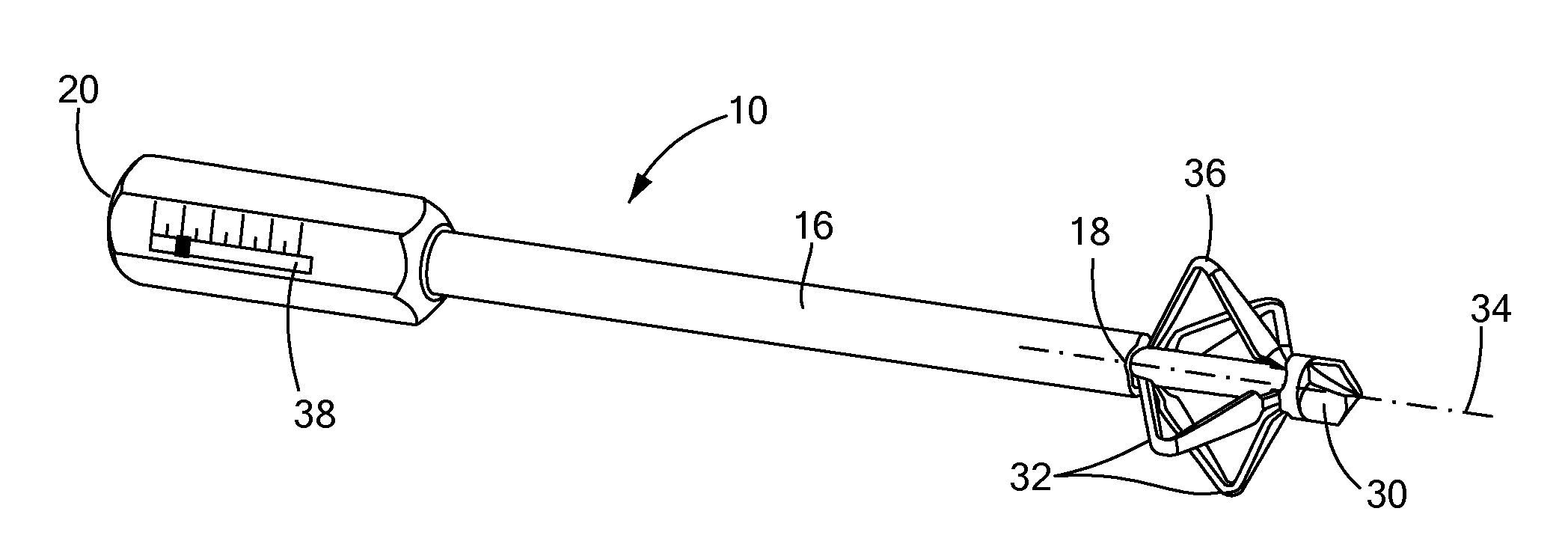
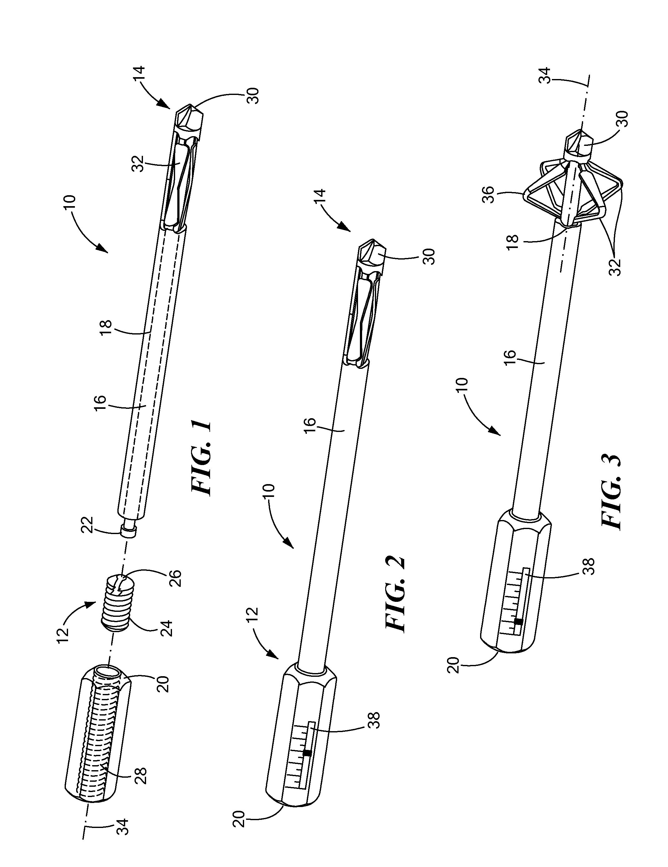
[0014]The present disclosure advantageously provides methods and systems that can be used to create one or more drilling sites or cavities having varying dimensions in an efficient and minimally-invasive manner. For example, now referring to FIGS. 1-3, a surgical or medical instrument is shown and generally designated as “10.” The instrument 10 may generally be an orthopedic drilling instrument, such as a reamer or other tissue preparation and / or removal device.

[0015]The instrument 10 generally defines a proximal portion 12 and a distal portion 14, where the proximal portion 12 is closer to or in proximity to a surgeon or user, while the distal portion 14 is closer to or in proximity to a tissue site to be treated or operated upon. The instrument 10 may include a first elongated body or shaft 16 that extends from the proximal portion 12 of the instrument 10 to the distal portion 14. The first shaft 16 may have a generally cylindrical shape and may be constructed from any of a number...


PUM


Abstract

An orthopedic reamer, including a first shaft; a second shaft movably disposed within at least a portion of the first shaft; a handle movably coupled to at least one of the first or second shafts; a drilling element coupled to a distal portion of the second shaft; and a plurality of cutting elements, each cutting element having a first portion connected to the first shaft and a second portion connected to the second shaft. The plurality of cutting elements are controllably transitionable from i) a substantially linear configuration parallel to the first and second shafts to ii) an angled configuration with respect to the first and second shafts.

Description

CROSS-REFERENCE TO RELATED APPLICATION[0001]N / ASTATEMENT REGARDING FEDERALLY SPONSORED RESEARCH OR DEVELOPMENT[0002]N / AFIELD OF THE INVENTION[0003]The present invention relates to instrumentation and methods of use thereof for preparing or removing tissue, and in particular, towards surgical reamers or orthopedic drilling instruments.BACKGROUND OF THE INVENTION[0004]An objective of surgery in general, including orthopedic surgery, is to provide instruments, devices, and methods that are minimally invasive to the patient. Such efforts may include, for example, minimizing or reducing an incision or other access point site and / or reducing the time required for a given procedure. For drilling or reaming procedures, the size or geometry of an insertion or access incision may require sufficient dimensions to allow passage of a drill bit having a fixed width or profile. Where expansive drilled cavities are desired or necessary for placement of a prosthesis or other orthopedic hardware, the...

Claims


Application Information

Patent Timeline
Patent Type & Authority Applications(United States)
IPC IPC(8): A61B17/16
CPCA61B17/00234A61B17/1631A61B17/1626A61B17/1617
Inventor GRIFFITHS, JERRY R.FERNANDEZ, JOSE
Owner SYMMETRY MEDICAL MFG INC
Learn More