
Threshold-based zero-crossing detection in an electrical dimmer

a technology of dimmer and threshold, applied in the direction of lighting apparatus, electroluminescent light sources, light sources, etc., can solve the problems of insufficient zero-crossing detection via traditional means of detecting a change in polarity, and the prior art method of dimmer zero-crossing detection in two-wire devices (which have input line and output), so as to improve the synchronization capability of dimmer and avoid false triggering

Active Publication Date: 2013-06-27
LEVITON MFG
View PDF4 Cites 18 Cited by
  • Summary
  • Abstract
  • Description
  • Claims
  • Application Information

AI Technical Summary

Benefits of technology

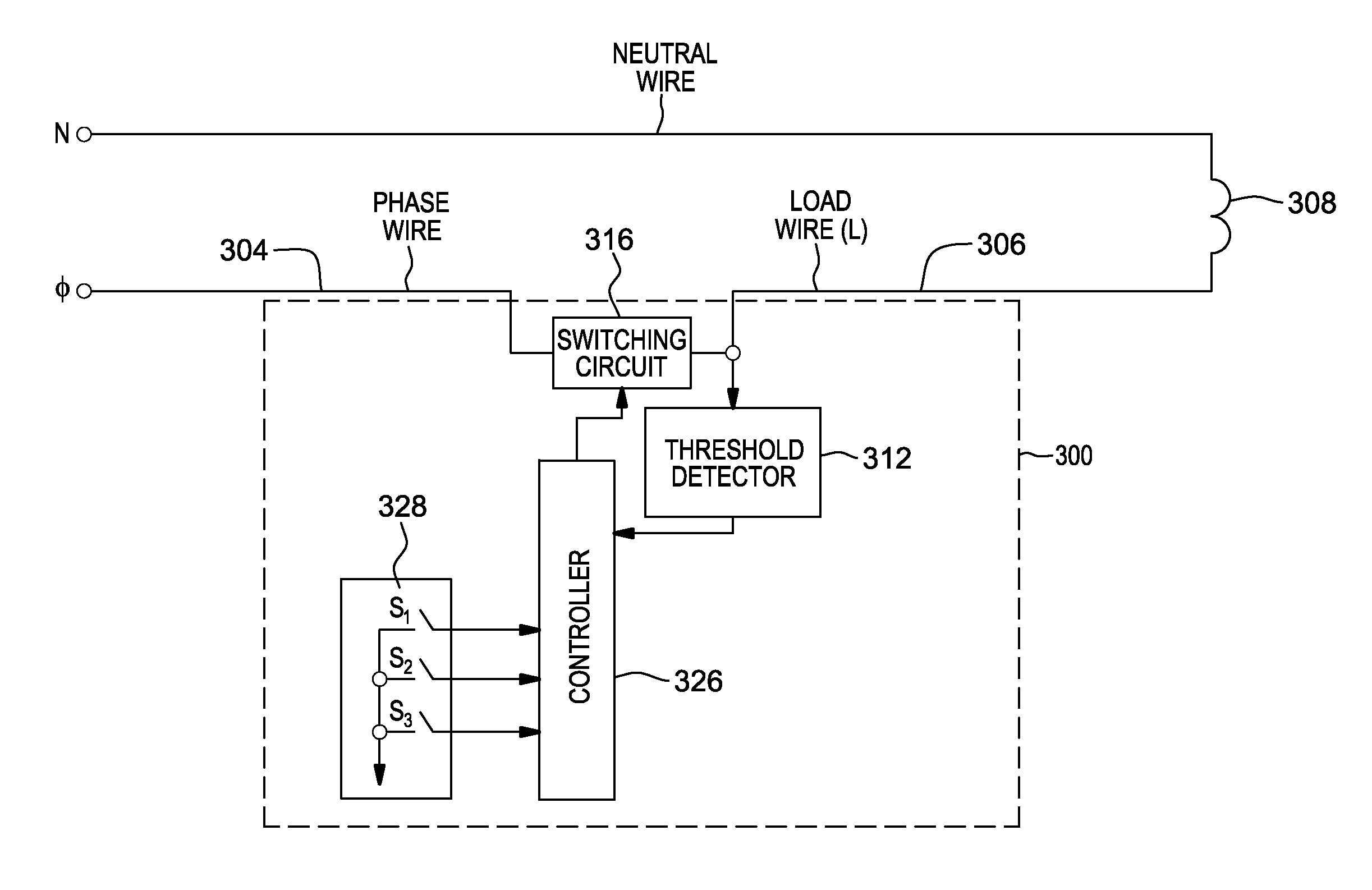
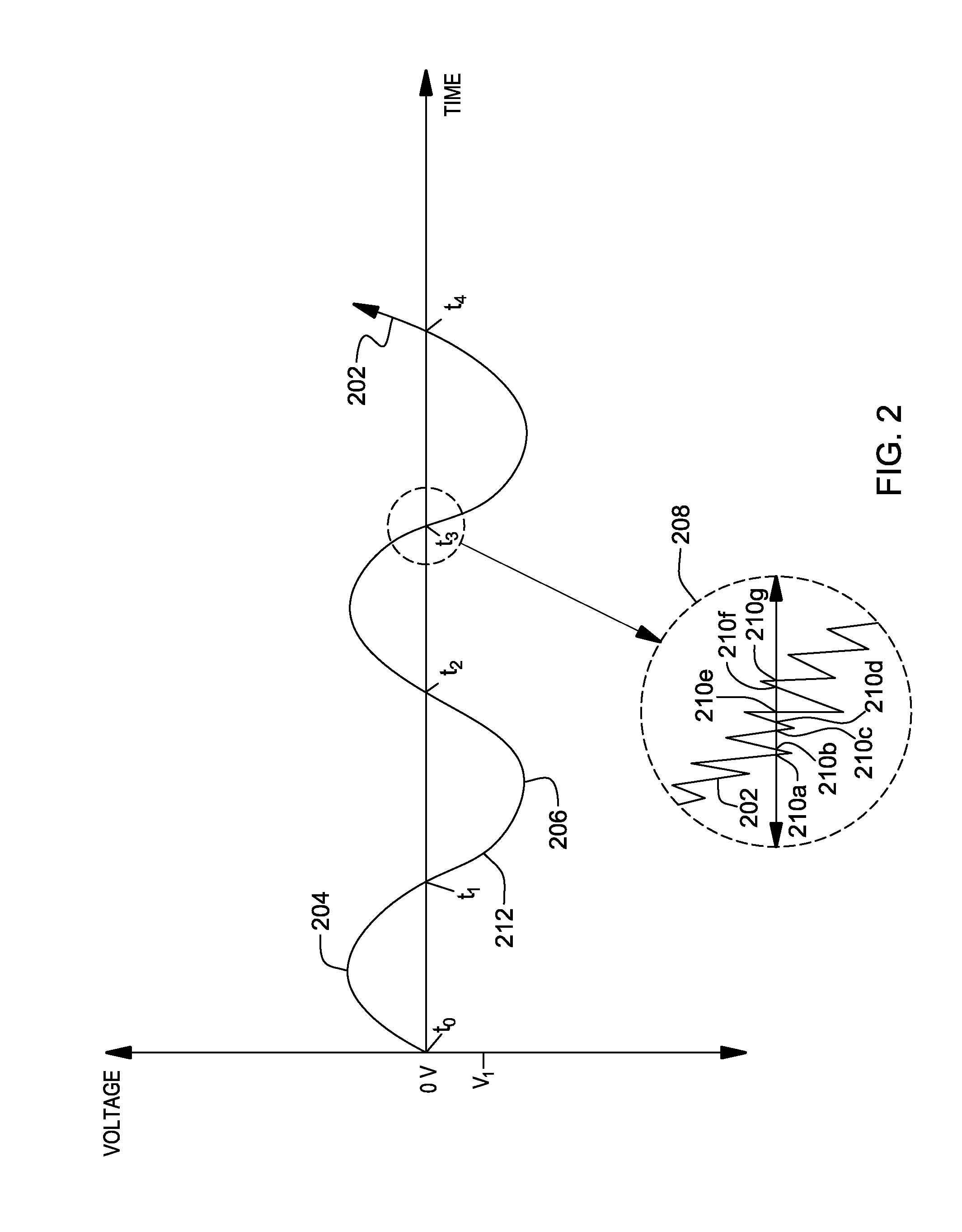
The present invention introduces a function that helps improve the synchronization of a dimmer and prevents false triggering caused by voltage fluctuations near zero. Instead of detecting the position where the input voltage crosses zero, the invention detects when the input voltage reaches a defined positive or negative threshold. This threshold trigger point is placed above or below the zero voltage level, which prevents false triggering that results from voltage polarity reversals near zero voltage.

Problems solved by technology

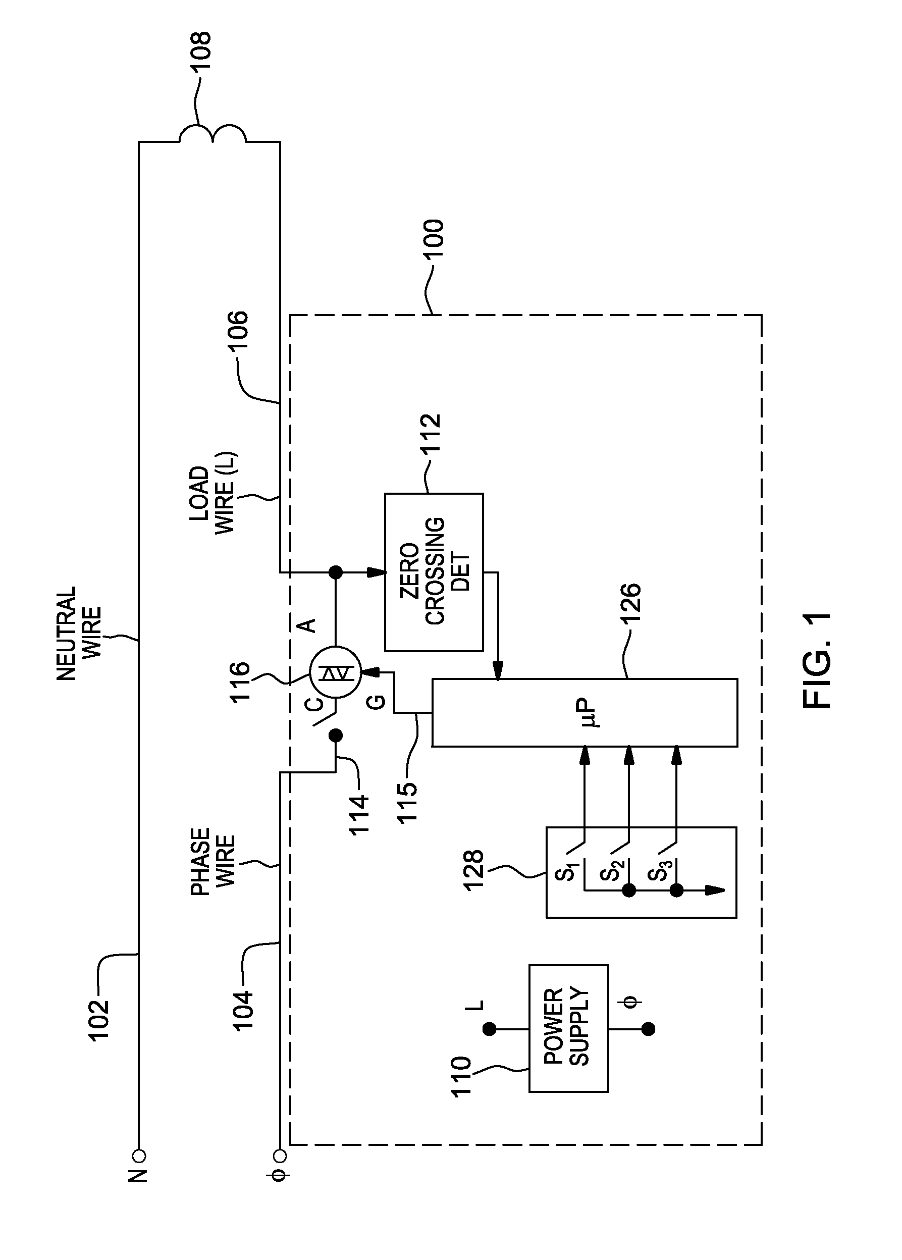
The prior art method of zero-crossing detection in two-wire devices (which have input line and output load terminals, but do not have a separate neutral connection or ground leakage path) can be problematic.
Consequently, zero-crossing detection via the traditional means of detecting a change in polarity can be inadequate.
Multiple reversals of the polarity of the input-to-output voltage may occur near a zero-crossing, and these can cause a conventional zero-crossing detection circuit to falsely trigger.

Method used


Image

  • Threshold-based zero-crossing detection in an electrical dimmer
  • Threshold-based zero-crossing detection in an electrical dimmer
  • Threshold-based zero-crossing detection in an electrical dimmer

Examples


Embodiment Construction

[0016]Disclosed herein are various dimmers for controlling electrical power to a load. As explained in detail below, in accordance with one aspect of the present invention, a threshold function is employed to provide zero-crossing indication(s) for use in controlling switching of the electrical power to the load.

[0017]FIG. 1 depicts one example of a dimmer comprising a zero-crossing detection circuit facilitating controlling electrical power to a load. In FIG. 1, load control switch 100 (also referred to herein as a “dimmer” or “dimmer switch”) is able to activate, and control power to, an electrical device 108. Control switch 100 includes a microprocessor 126 coupled to user accessible actuators 128. Microprocessor 126 may include, but is not limited to, a complex instruction set computer processor and a reduced instruction set computer processor. A user of control switch 100 is able to engage one or more actuators of actuators 128, which microprocessor 126 may interpret as a comma...


PUM


Abstract

Threshold-based zero-crossing detection is provided. A power phase threshold detector detects when absolute value of a voltage level of the electrical power rises above a non-zero voltage threshold and outputs a zero-crossing signal to a controller to indicate occurrence of the zero-crossing. Delaying the zero-crossing signal to the point when the absolute value of the voltage level of the electrical power rises above the non-zero voltage threshold ensures completion of the zero-crossing of the power phase prior to signaling the controller. The controller provides signals to a switching circuit for controlling switching of electrical power to a load based on the zero-crossing indications.

Description

BACKGROUND[0001]In an electrical load dimmer, a technique known as zero-crossing detection is conventionally employed, wherein the dimmer is synchronized with one or more phases of an input line voltage to enable the dimmer to properly fire a load-controlling switch, such as a TRIAC, at specific Ftimes with respect to the input line phase. More specifically, a zero-crossing is detected by detecting a change in voltage polarity of the input line voltage. In other words, zero-crossing is detected when the input line voltage changes polarity at the zero volt level, which triggers a signal in the microprocessor that the voltage level has crossed zero volts.[0002]In prior art designs, zero-crossings of an input line phase are detected by detecting a change in the polarity of the voltage across an input line terminal and an output load terminal (that is, in two-wire devices without a neutral connection), or across the input line terminal and return neutral or ground wire terminal (in thre...

Claims


Application Information

Patent Timeline
Patent Type & Authority Applications(United States)
IPC IPC(8): H05B37/02
CPCY02B20/346H05B33/0815H05B45/3725Y02B20/30
Inventor GALLO, MARC
Owner LEVITON MFG
Learn More