
Connect/disconnect connector for coaxial cable

Inactive Publication Date: 2013-06-20
HEEBE CLARKE +1
View PDF8 Cites 24 Cited by
  • Summary
  • Abstract
  • Description
  • Claims
  • Application Information

AI Technical Summary

Benefits of technology

The present invention provides a connector that allows for easy and secure connection between two electrical conductors, such as two or more segments of a coaxial cable. The connector has a hollow housing and a coupler that move in a limited distance in a sliding relation to each other. A locking member is fitted between the housing and the couplier to lock position of the housing in relation to the coupler and disengage the housing from the coupler when needed. The locking member has a compression spring that normally urges the housing away from the couplier and locking balls fitted in cutouts made in the locking member. The invention is designed to be easily manipulated by people with restricted hand movement.

Problems solved by technology

Also, a lay person may not want to invest in expensive tools that allow cable crimping.
Even further, the connectors being usually on the back of a television set are not easily reachable.
To unthread the connectors and remove the coaxial cable from the back of a television set may be awkward.
This task may be particularly troublesome for people having limited movement in their hands.
While the device of the '588 patent works satisfactory in many instances it was determined that some users, particularly those having reduced strength in their hands, experience some difficulty in engaging the connector with the receptacle on TV, cable box, and other electronic equipment using coaxial connectors.

Method used


Image

  • Connect/disconnect connector for coaxial cable
  • Connect/disconnect connector for coaxial cable
  • Connect/disconnect connector for coaxial cable

Examples


Embodiment Construction

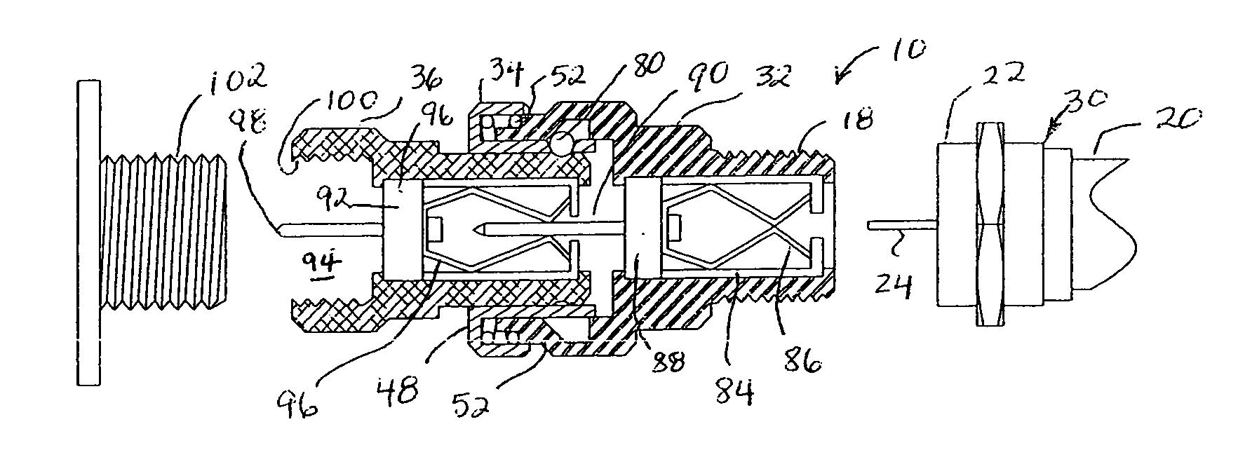
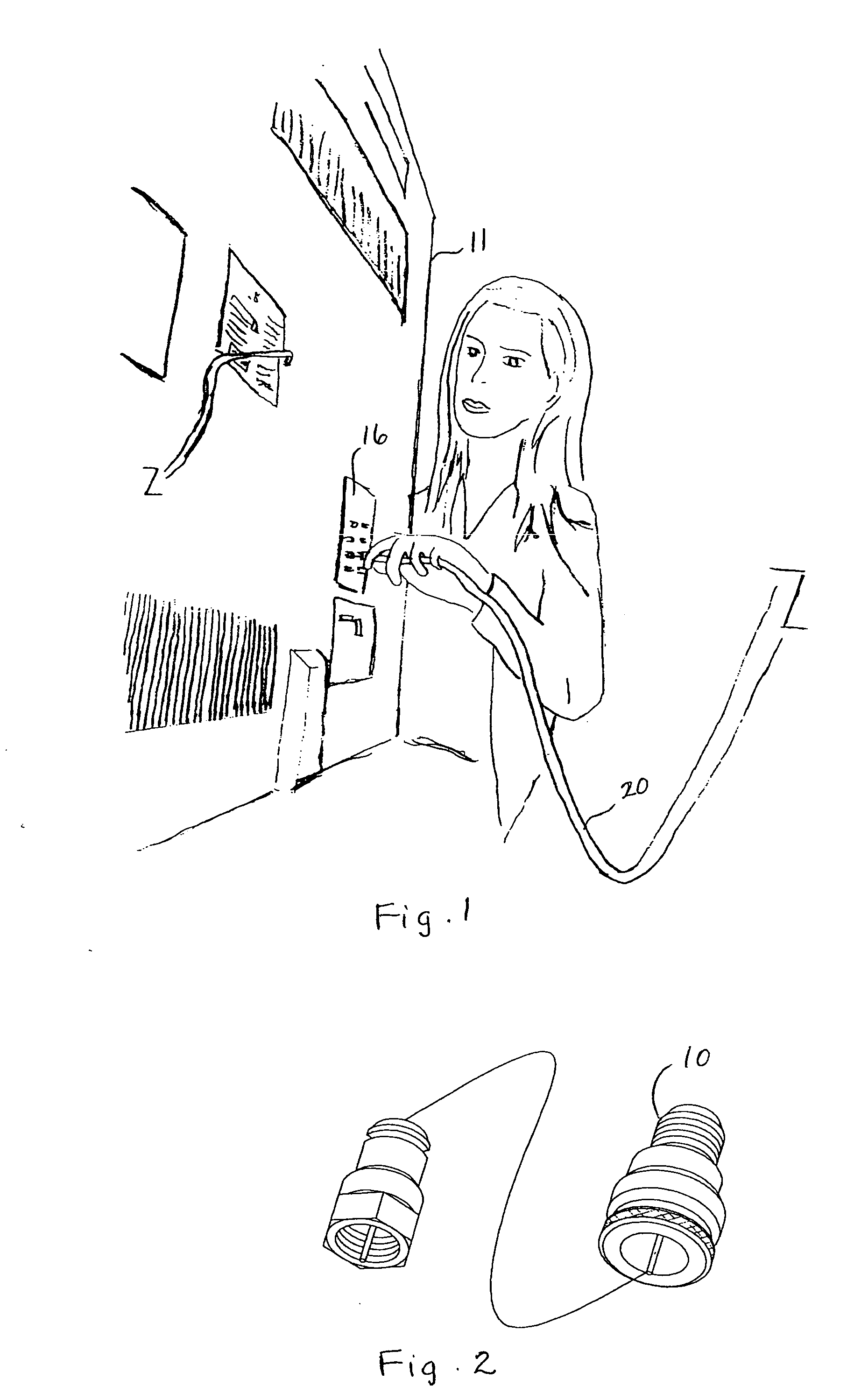
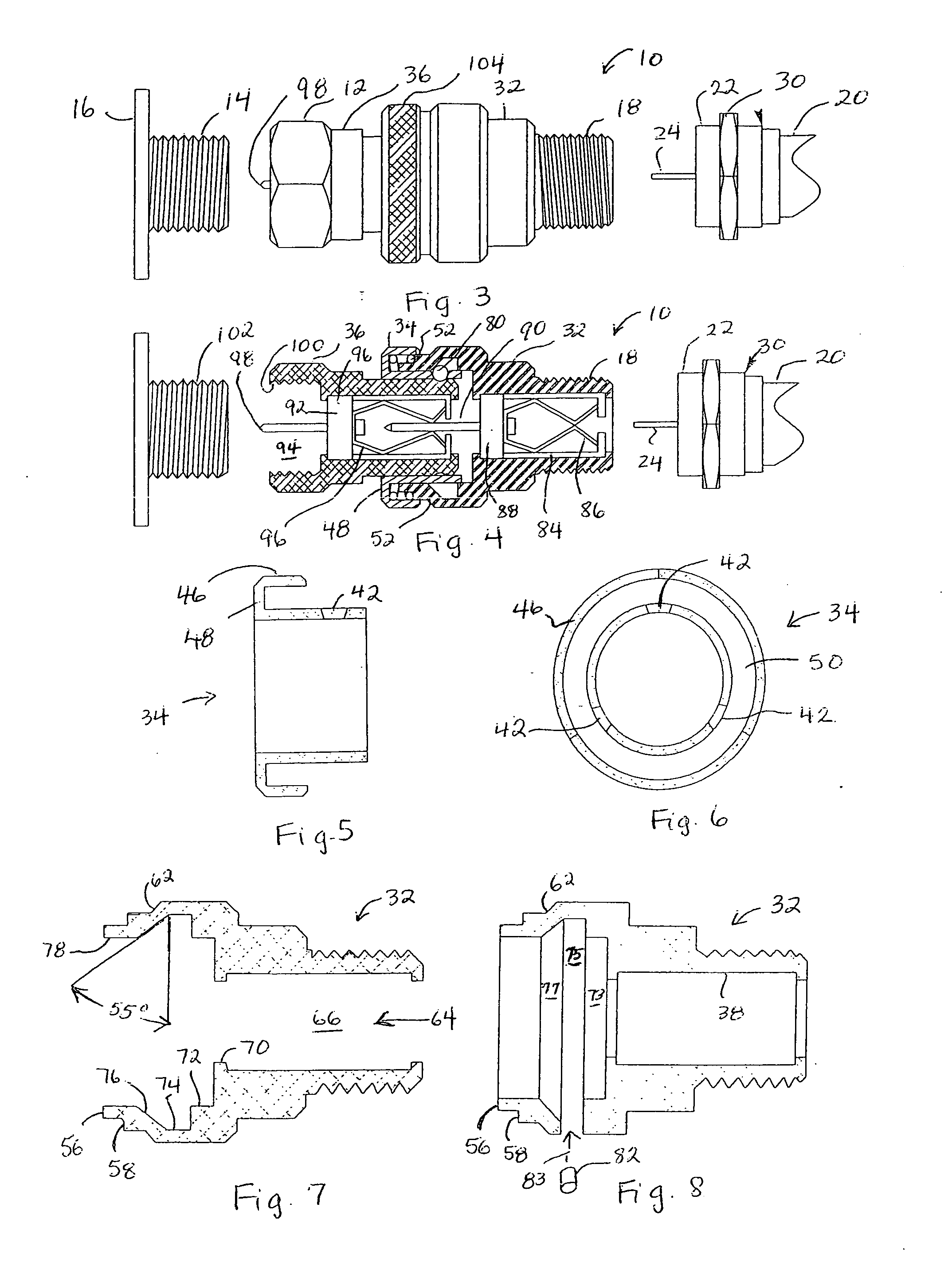
[0026]Turning now to the drawings in more detail, the locking connector assembly or connector of the present invention is generally designated by numeral 10. The assembly 10 comprises a first end 12 adapted for connecting to a receptacle 14 mounted on a television, DVD player or other similar electronic equipment secured on a mounting wall 16 of an electronic device 17.

[0027]The assembly 10 comprises a second externally threaded end 18, which is adapted for connection to a coaxial cable 20. Conventionally, the end of the coaxial cable 20 is provided with a coupler component 22, which allows the electrical conductor core 24 to extend outwardly. The coupler component 22 has inner threads (not shown), with which the threads 18 are configured to matchingly engage. When a nut 30 of the coupler component 22 is rotated the threads of the coupler component 22 are forced to engage with the threads of the threaded end 18 of the connector 10.

[0028]The assembly 10 comprises a receiver housing 3...


PUM


Abstract

A connector for quick connect / disconnect engagement between two or more segments of coaxial cable has a hollow housing for attaching to a first electrical conductor and a coupler for attaching to a second electrical conductor. The housing and the coupler move to a limited distance in a sliding relation to each other. A locking member is fitted between the housing and the coupler to lock position of the housing in relation to the coupler and disengage the housing from the coupler when needed. The locking member has a compression spring that normally urges the housing away from the coupler and locking balls fitted in cutouts made in the locking member. When the spring is compressed, the locking balls move from the cutouts into an annular groove formed in the inner wall of the housing, thus allowing a limited sliding movement of the housing.

Description

BACKGROUND OF THE INVENTION[0001]This invention relates to couplings, and more particularly to a connector that can be used for connecting segments of coaxial cables together, or for connecting coaxial cables to televisions, video players, DVD players, and other types of electronic equipment.[0002]Many types of electronic equipment are connected with coaxial cables. The coaxial cables conventionally have an electrically conductive core. The core must be electrically connected with a receptacle mounted on the body of the television, DVD player, and other similar equipment.[0003]The core is encased in a non-conductive insulation. Before connecting the cable to a piece of an electronic equipment, the electrician has to crimp the end of the cable and attach a connector that has a threaded nut for engaging with the threaded receptacle on the electronic equipment to establish the electrical connection.[0004]However, the electrician must have certain experience to perform the task of prepa...

Claims


Application Information

Patent Timeline
IPC IPC(8): H01R13/62
CPCH01R9/05H01R31/06H01R13/635
Inventor HEEBE, CLARKEARROYO, MELVIN L.
Owner HEEBE CLARKE
Learn More