X-ray CT apparatus and tube current determination method
a technology of ct apparatus and current determination method, which is applied in the field of xray ct imaging technique, can solve the problem that the desired diagnosticability cannot be obtained, and achieve the effect of suppressing the amount of exposure of the object, high diagnosticability, and reducing the amount of operability
- Summary
- Abstract
- Description
- Claims
- Application Information
AI Technical Summary
Benefits of technology
Problems solved by technology
Method used
Image
Examples
first embodiment
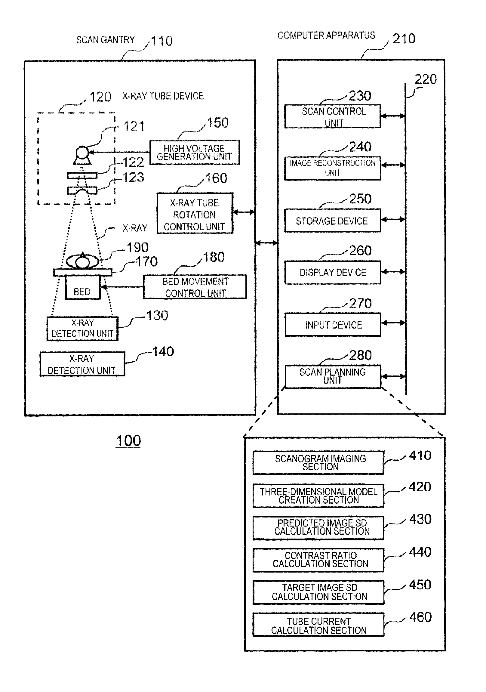
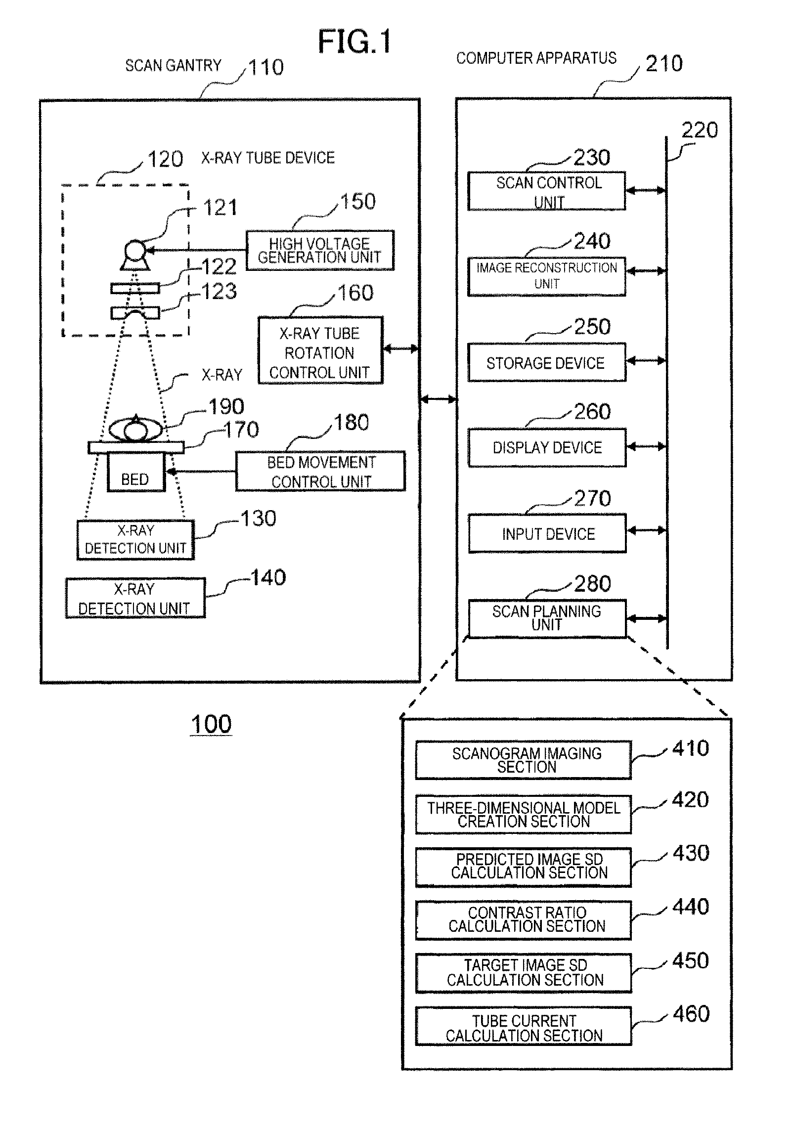
[0028]Hereinafter, a first embodiment to which the present invention is applied will be described. Hereinafter, in all drawings for explaining the embodiments of the present invention, the same reference numerals are given to elements having the same functions, and repeated explanation thereof will be omitted.
[0029]First, an X-ray CT apparatus of the present embodiment will be described. The X-ray CT apparatus includes an X-ray tube that irradiates an object with X-rays and an X-ray detector that detects X-rays transmitted through the object. The detected X-rays are output as projection data. This is an apparatus that collects projection data from many directions by rotating the X-ray tube and X-ray detector opposite each other around the object and reconstructs a tomographic image of the object by back-projection.
[0030]Examples of the X-ray CT apparatus include a single slice type X-ray CT apparatus to obtain one tomographic image by the single X-ray exposure and a multi-slice type...
second embodiment
[0099]Next, a second embodiment to which the present invention is applied will be described. An X-ray CT apparatus of the present embodiment has basically the same configuration as that in the first embodiment. In addition, also in the present embodiment, the imaging conditions are determined by calculating the tube current on the basis of the image quality level input by the operator in the same procedure as in the first embodiment. In the present embodiment, however, an operator's change of the tube current calculated in the procedure of the first embodiment is received. Therefore, a computer apparatus 210 of the present embodiment includes a scan planning unit 281 instead of the scan planning unit 280 of the first embodiment. Hereinafter, the present embodiment will be described focusing on the different configuration from the first embodiment.
[0100]FIG. 4 shows a functional block of the scan planning unit 281 of the present embodiment. As shown in this drawing, the scan planning...
third embodiment
[0131]Next, a third embodiment to which the present invention is applied will be described. The present embodiment has basically the same configuration as each of the embodiments described above, but the method of specifying the standard object size is different. That is, in the embodiments described above, the standard object size is calculated from the long-axis length and the short-axis length of the water-equivalent ellipse registered in advance as a standard object model or from the standard body weight and the like registered in advance. In the present embodiment, however, the standard object size is determined by setting the predetermined slice position (reference SD setting line) on the scanogram image. Therefore, a computer apparatus 210 of the present embodiment includes a scan planning unit 282 instead of the scan planning unit 280 of the first embodiment. Hereinafter, the present embodiment will be described focusing on the different configuration from the first embodime...
PUM
 Abstract
Description
Claims
Application Information
 - R&D
- Intellectual Property
- Life Sciences
- Materials
- Tech Scout
- Unparalleled Data Quality
- Higher Quality Content
- 60% Fewer Hallucinations
Browse by: Latest US Patents, China's latest patents, Technical Efficacy Thesaurus, Application Domain, Technology Topic, Popular Technical Reports.
© 2025 PatSnap. All rights reserved.Legal|Privacy policy|Modern Slavery Act Transparency Statement|Sitemap|About US| Contact US: help@patsnap.com


