
Antenna device

a technology of antennas and antennas, applied in the direction of slot antennas, antenna details, antennas, etc., can solve the problems of difficulty in achieving the isolation the length of the monopole antenna is too long in consideration of the mechanism limit, and the plurality of antennas are often needed. , to achieve the effect of reducing the height of each of improving isolation between the two monopole antennas, and convenient housing

Active Publication Date: 2013-06-20
WISTRON NEWEB
View PDF5 Cites 15 Cited by
  • Summary
  • Abstract
  • Description
  • Claims
  • Application Information

AI Technical Summary

Benefits of technology

This patent is about an antenna device that uses a multiple input multiple output (MIMO) antenna system. The design of the antenna device reduces the height of the two monopole antennas, making them easier to accommodate and improving isolation between them. This reduces the effect of cross polarization and improves the quality of communication. Additionally, the antenna device can be designed for dual band use and includes supporting boards and isolating members to further improve stability and isolation between the two monopole antennas. Overall, this patent presents a technical solution for improving the performance and reliability of MIMO antennas in various applications.

Problems solved by technology

However, with regard to the monopole antenna for receiving a low-band frequency (e.g., 700 MHz), the length of the monopole antenna is too long in consideration of the mechanism limit resulted from wind pressure generated by a moving car.
However, within a limited space, a plurality of antennas are often needed to be placed for receiving different types of wireless communication signals.
Since long term evolution (LTE) techniques use many frequency bands and most of them are broadband designs, such that they are very challenging to the two monopole antennas with multiple input multiple output (MIMO).
For example, because being significantly high, the low frequency receiving portion of the LTE antenna is limited by the space of the fin-shaped shell.
Therefore, when being disposed in the fin-shaped shell, the two monopole antennas may easily lose the original features of MIMO antenna due to significantly high mutual coupling effect.

Method used


Image

  • Antenna device
  • Antenna device
  • Antenna device

Examples


Embodiment Construction

[0039]In the following detailed description, for purposes of explanation, numerous specific details are set forth in order to provide a thorough understanding of the disclosed embodiments. It will be apparent, however, that one or more embodiments may be practiced without these specific details. In other instances, well-known structures and devices are schematically shown in order to simplify the drawings.

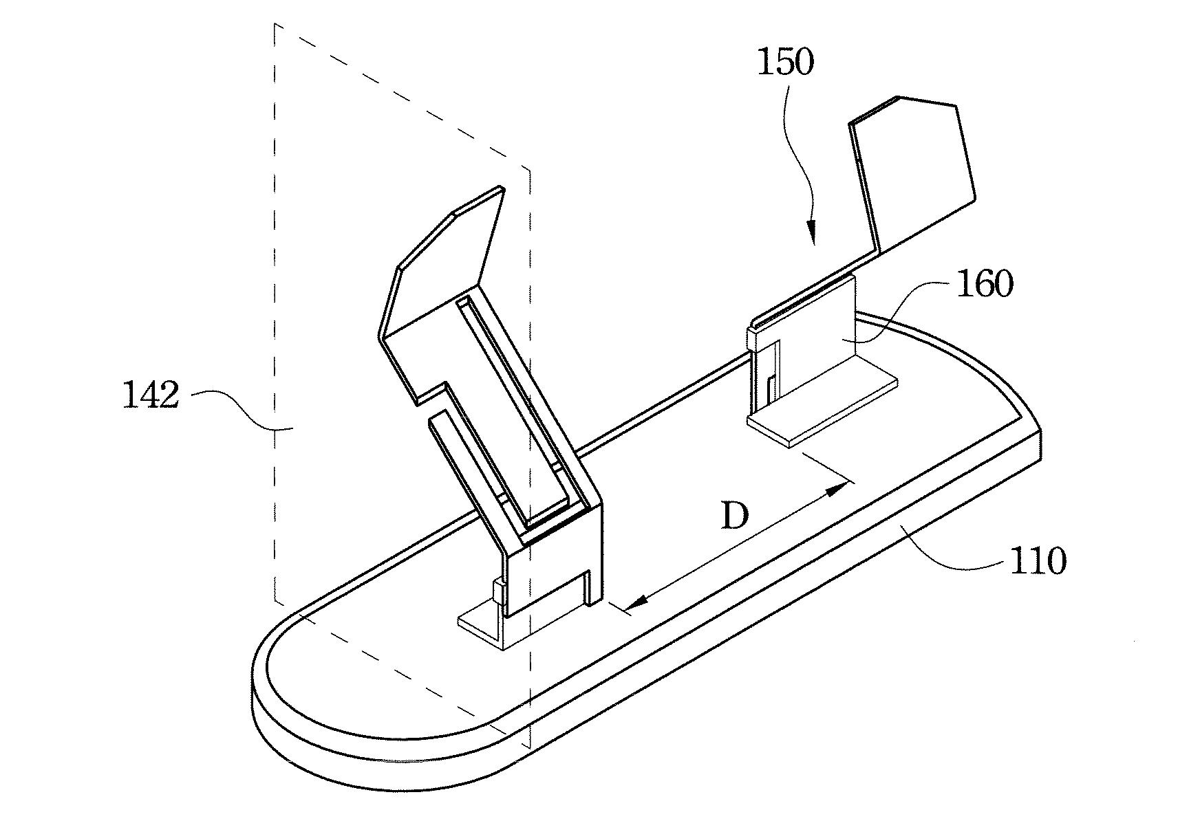
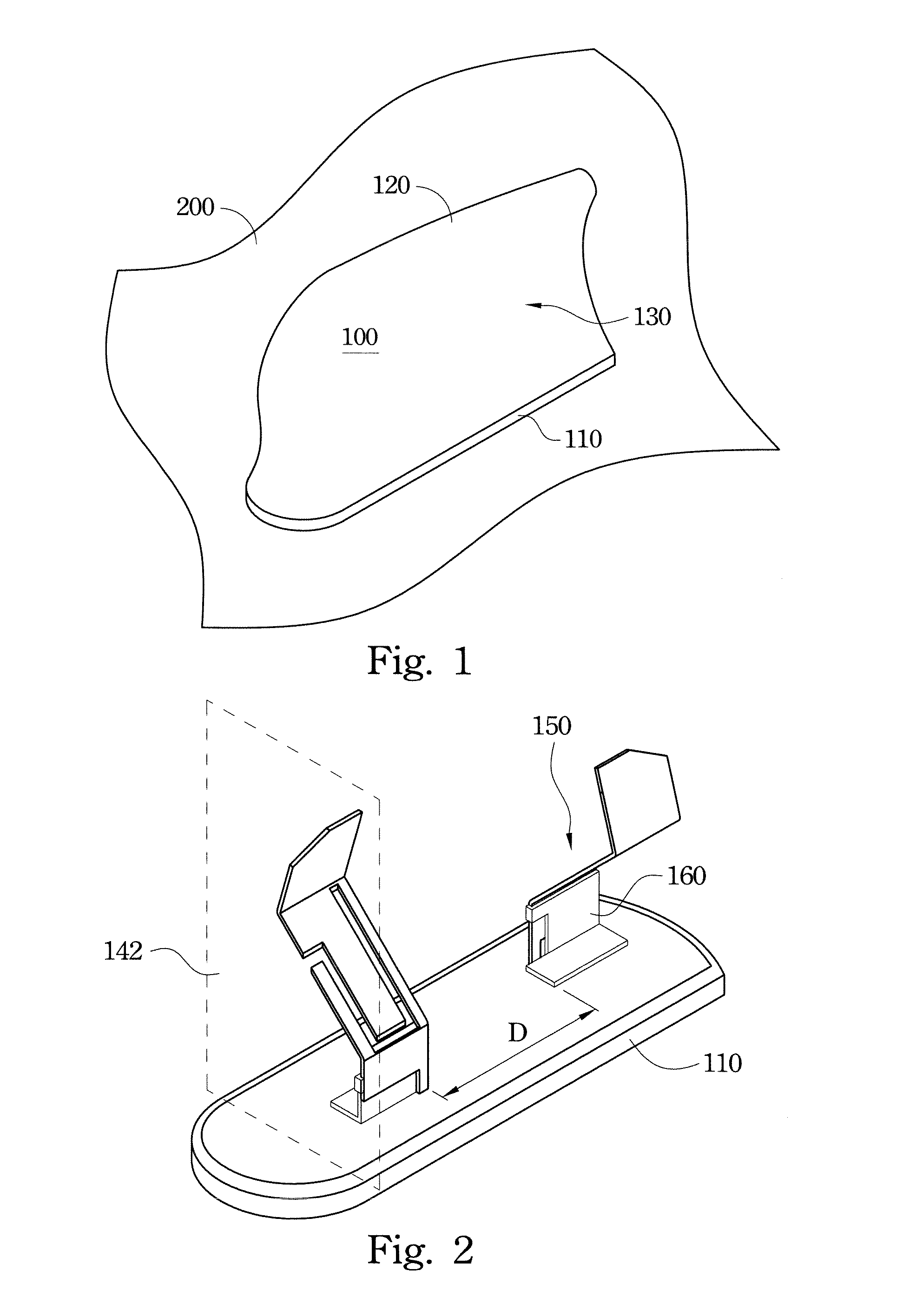
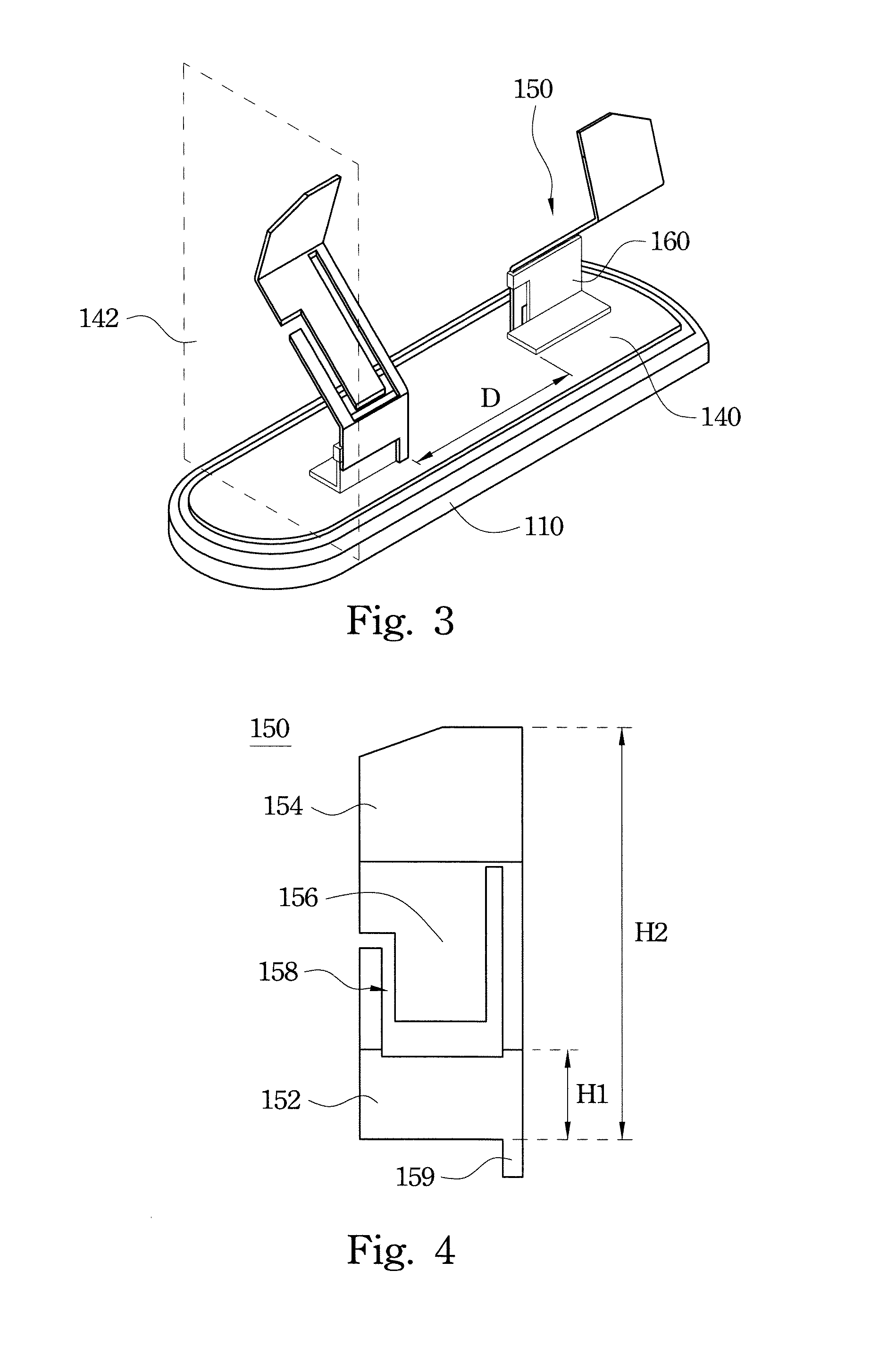
[0040]FIG. 1 is a 3-D view of an antenna device 100 according to an embodiment of the present invention. FIG. 2 is a 3-D view of the antenna device 100 shown in FIG. 1 after a cover 120 is removed. As shown in FIG. 1 and FIG. 2, the antenna device 100 is a multiple input multiple output (MIMO) antenna, and the antenna device 100 may be located on a car roof 200. The antenna device 100 includes a bottom 110, two monopole antennas 150, and the cover 120. A projection plane 142 is defined perpendicular to the bottom 110. The two monopole antennas 150 substantially symmetrically protru...


PUM


Abstract

An antenna device is provided and includes a bottom, two monopole antennas, and a cover assembled with the bottom. A projection plane is defined perpendicular to the bottom. The two monopole antennas substantially symmetrically protrude from the bottom, and a gap is formed between the two monopole antennas. Projections of the two monopole antennas on the projection plane intersect with each other. Each of the two monopole antennas includes a first frequency receiving portion adjacent to the bottom, a second frequency receiving portion, and a connection portion located between the first frequency receiving portion and the second frequency receiving portion. A slot is formed through the connection portion to adjust a received frequency of the first or second frequency receiving portion. An accommodating space is formed between the cover and the bottom to accommodate the two monopole antennas.

Description

RELATED APPLICATIONS[0001]This application claims priority to Taiwan Application Serial Number 100146526, filed Dec. 15, 2011, which is herein incorporated by reference.BACKGROUND[0002]1. Technical Field[0003]The present disclosure relates to an antenna device, and more particularly to an antenna device including two monopole antennas.[0004]2. Description of Related Art[0005]In recent years, different types of wireless communication signals applied in technically advanced consumer electronic products have been prosperously developed, such as the signals of AM / FM, global system for mobile communications (GSM), global positioning system (GPS), satellite digital audio radio service (SDARS), digital video broadcasting (DVB), etc. In addition, the wireless communication devices applied to automotive electronics are also benefited by the evolutions of consumer electronic products and wireless communication signals. Therefore, it has become a development trend of the automotive electronics...

Claims


Application Information

Patent Timeline
Patent Type & Authority Applications(United States)
IPC IPC(8): H01Q13/10H01Q21/00H01Q5/10
CPCH01Q1/3275H01Q21/28H01Q1/521
Inventor JAN, CHENG-GENGCHEN, I-SHANLIN, CHIA-HONGLIN, TIEN-MINWANG, YI-CHEIHHSU, CHENG-HSIUNG
Owner WISTRON NEWEB
Learn More