Split Frame Lathe

a technology of lathes and frames, applied in the field of lathes with split frames, can solve the problems of loss of productivity, inability to easily use designs on elbows or curves, and the use of lathes

Inactive Publication Date: 2013-06-20
WOKAN MIROSLAW +3
View PDF6 Cites 24 Cited by
  • Summary
  • Abstract
  • Description
  • Claims
  • Application Information

AI Technical Summary

Benefits of technology

The patent describes a split frame lathe that includes a stationary base ring, a gear ring, and a cutting tool. The lathe has internal bearing systems that connect the gear ring to the base ring and secure the tool in place. The position of the tool can be adjusted by changing the orientation of the internal bearing system. The gear ring has slots and pins that engage with the internal bearing system to secure the tool. The lathe also includes a hinge system that allows the base ring to move and pivot. The technical effects of the invention include improved positioning of the tool, reduced movement of the tool during operation, and improved stability of the lathe.

Problems solved by technology

The need for these lathes in these industries often require the lathes be used in harsh environments including nuclear power plants, underwater, offshore oil rigs, or other hazardous conditions.
For example, some existing lathes incorporate clamping mechanisms that can accidentally disengage while the machine is in use and may strip or break off entirely, which can lead to loss of productivity while the machine undergoes what can be expensive repairs.
Some designs cannot readily be used on an elbow or curve, instead requiring labor and time intensive adjustment by way of tapping the clamping mechanisms with a piece of brass and a hammer in order to adjust for curvature.
In some lathe designs, some of the parts wear quickly and are difficult to replace or can become damaged, which again increases down time during projects while the machine undergoes maintenance and repairs.
Some lathes also have a propensity for becoming misaligned due to inadequate locking or connecting mechanisms that lack durability.
Not only does a misaligned lathe increase the potential for substantial damage to the machine, but it can also pose danger to the operator.

Method used


Image

  • Split Frame Lathe
  • Split Frame Lathe
  • Split Frame Lathe

Examples


Embodiment Construction

[0053]While the present invention is susceptible of embodiment in various forms, there is shown in the drawings and will hereinafter be described a presently preferred embodiment with the understanding that the present disclosure is to be considered an exemplification of the invention and is not intended to limit the invention to the specific embodiment illustrated.

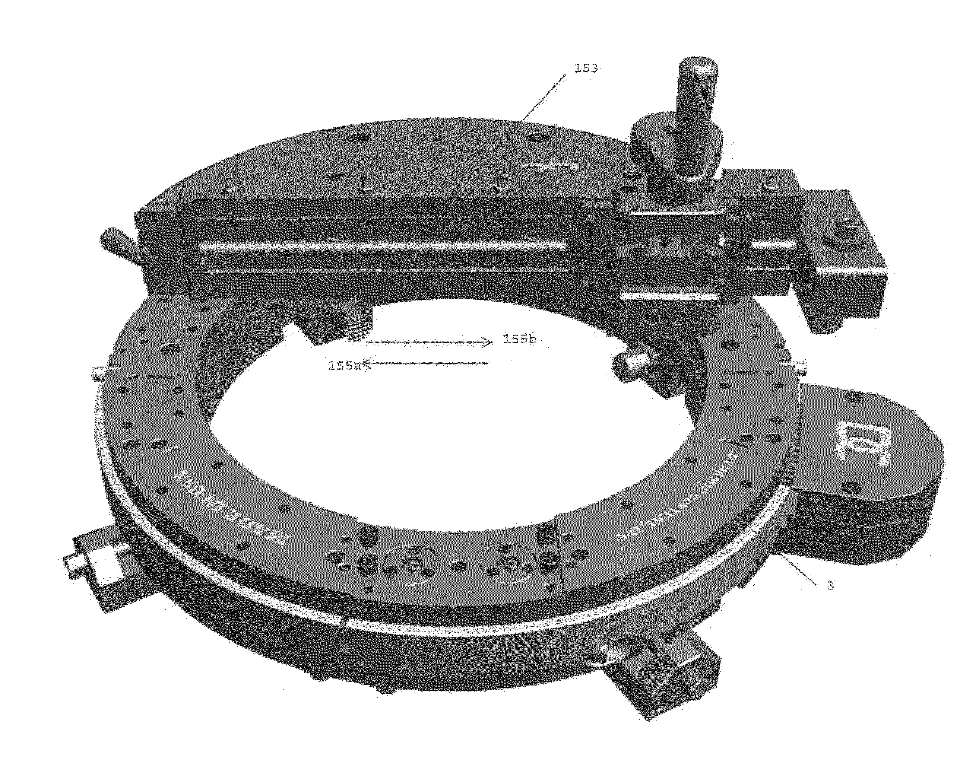
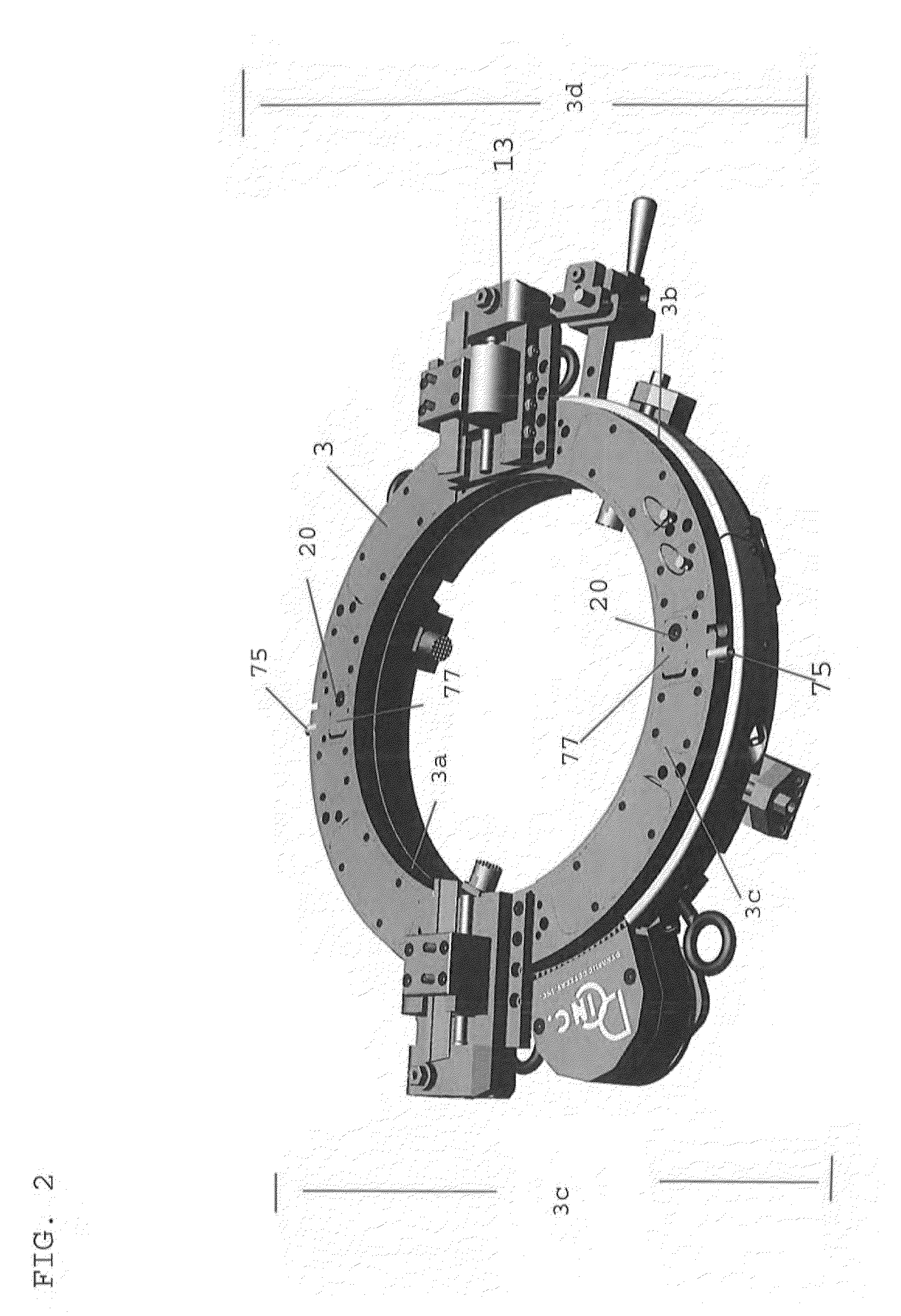
[0054]One embodiment the inventive split frame lathe is illustrated in FIG. 1. The split frame lathe includes a ring assembly comprising a base ring 1 having a first half 1c and a second half 1d (as shown in FIG. 5). The base ring is rotatably connected by an internal bearing system (as shown in FIG. 3) to a gear ring 3 having a first half 3c and a second half 3d (as shown in FIG. 4). One or more leg assemblies 5 are externally mounted to the base ring 1 to enable the split frame lathe to attach to a pipe or other workpiece. In this embodiment, the lathe also comprises a hinge assembly 7, a trip system 9, a gear housing a...


PUM


Abstract

A split frame lathe having improved locking, cutting and adjustment capabilities is disclosed. The split frame lathe includes an embodiment having a plurality of internal bearing systems where each internal bearing system includes an eccentric bushing, a bearing pin and a v-bearing. Another embodiment of the split frame lathe may include adjustable leg systems. The split frame lathe may also include a star gear connected to a gear ring where the star gear can be rotated in a first direction and, alternatively, in an opposite second direction. In another embodiment the split frame lathe includes a trip system to prevent damage to the lathe and harm to the operator. The split frame lathe may also include improved locking mechanisms for the gear and base ring and a hinge system. The split frame lathe also may include a counter bore and flange facer attachment.

Description

BACKGROUND OF THE INVENTION[0001]This invention relates to split frame lathes typically used in the pipe cutting and weld prepping industries, and more particularly to a split frame lathe having improved locking and adjustment mechanisms and cutting capabilities.[0002]Split frame lathes are used in a variety of industries where precision welded piping systems are essential, such as power generating facilities, manufacturing facilities, and petrochemical plants. The need for these lathes in these industries often require the lathes be used in harsh environments including nuclear power plants, underwater, offshore oil rigs, or other hazardous conditions. These environments demand that downtime due to setup, operation and maintenance of equipment be minimized.[0003]There is a need for a more durable split frame lathe design, having more expansive cutting, shaping, locking and adjustment capabilities that promote more efficient and safe operation of the lathes and extend their working l...

Claims


Application Information

Patent Timeline
IPC IPC(8): B23B5/08
CPCB23B5/08B23B3/26Y10T82/22B23B5/162B23B3/265
Inventor WOKAN, MIROSLAWSHARD, ANDREWRASMUSSEN, ERICRASMUSSEN, MARK
Owner WOKAN MIROSLAW
Why Eureka
Try Eureka