
Sliding Bearing and Pump Device Using the Same

a technology of sliding bearing and pump device, which is applied in the direction of mechanical equipment, machines/engines, liquid fuel engines, etc., can solve the problems of limited fluid that can be used for the lubrication of sliding bearings, the sliding bearing itself which is used in the pump device is subject to conditions where it is difficult to obtain high dynamic pressure, and it is difficult for the structure to increase the load carrying capacity without. , the loading capacity and the rigidity of the entire sliding bearing can be increased, and the effect o

Inactive Publication Date: 2013-06-13
HITACHI-GE NUCLEAR ENERGY LTD
View PDF19 Cites 3 Cited by
  • Summary
  • Abstract
  • Description
  • Claims
  • Application Information

AI Technical Summary

Benefits of technology

The sliding bearing in this invention has an improved design that allows for increased loading capability and bearing rigidity. This is achieved by supporting the rotating shaft using hydrostatic pressure from outside and dynamic pressure produced on the inner surface of the sleeve. This results in a larger pressure, making it more durable and reliable than conventional examples.

Problems solved by technology

Moreover, for the purpose of preventing the entrance of foreign material, fluid that can be used for the lubrication of the sliding bearing is limited to fluid of the same kind as the fluid to be transferred by the pump.
In the aforesaid situation, the sliding bearing itself which is used in the pump device is subjected to conditions where it is hard to obtain high dynamic pressure as compared to an oil lubricating sliding bearing used in a general mechanical device.
However, even if the phases of the hydrostatic pressure pockets are shifted in the circumferential direction and the pockets are merely arranged in the plurality of rows as described in the patent literature 1, this structure has little influence on the load carrying capacity and bearing rigidity of the bearing and it is hard for the structure to increase the load carrying capacity without increasing the pressure of an oil supplied from the outside, or without increasing the size of the bearing.
However, even if the circumferential recess grooves are provided in the annular-band portions as described in JP-A No. 57-200699, change in pressure distribution on a bearing inner periphery is small and the effects of improving the load carrying capacity and bearing rigidity of the bearing cannot be anticipated at all.
Therefore, it is hard to improve the load carrying capacity without increasing the pressure of an oil supplied from the outside or without increasing the size of the bearing.
However, in the fluid bearing device disclosed in JP-A No. 60-37329, even if the dynamic pressure that is higher than the pressure of the pressure fluid supplied from the outside is produced in the dynamic pressure generating portion, the pressure is easy to escape through the supply groove and supporting by the dynamic pressure is restricted.
Therefore, it is difficult to apply the structures disclosed in the patent literatures to the vertical-type pumps or the like.

Method used


Image

  • Sliding Bearing and Pump Device Using the Same
  • Sliding Bearing and Pump Device Using the Same
  • Sliding Bearing and Pump Device Using the Same

Examples


embodiment 1

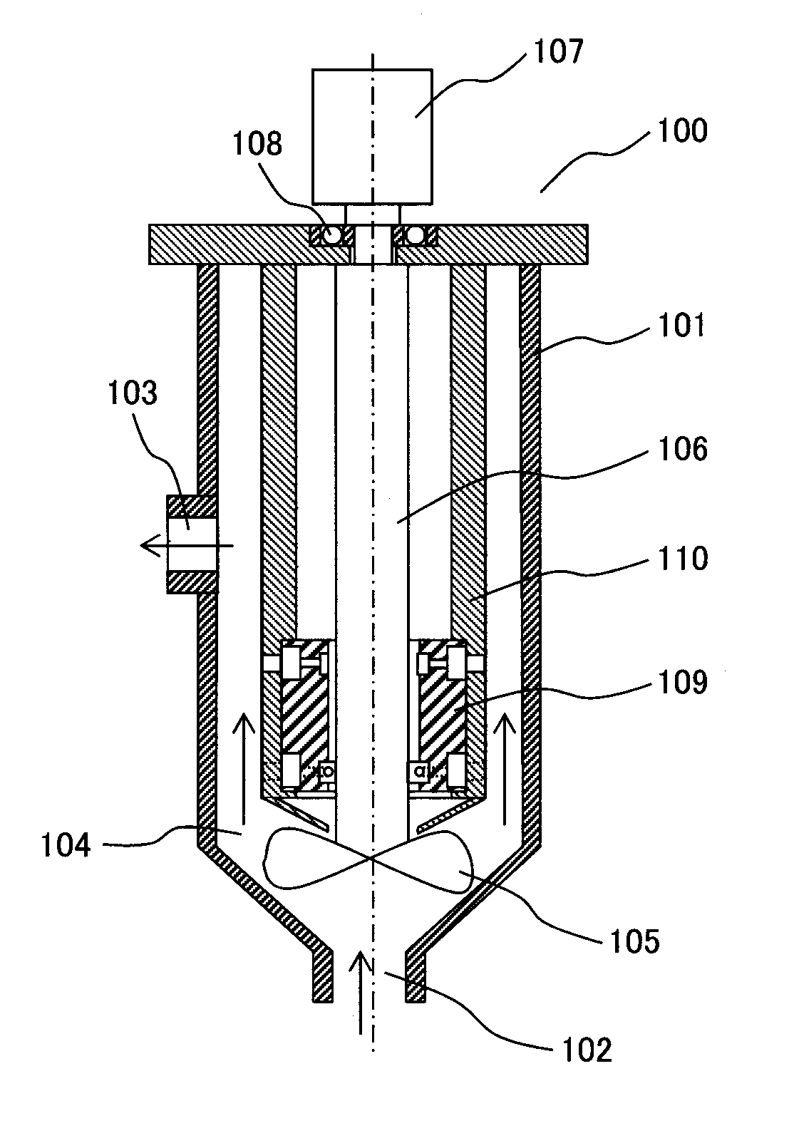
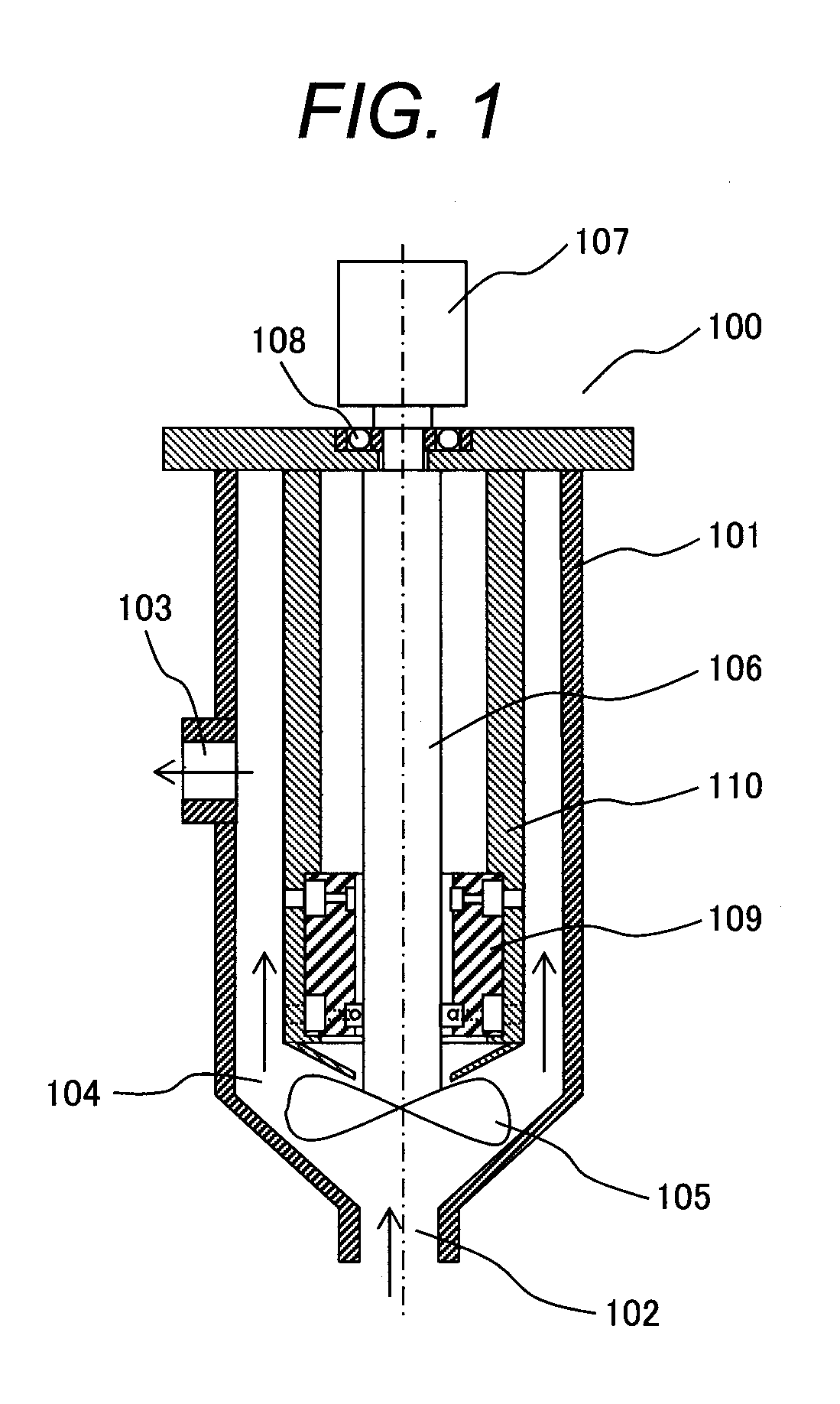
[0049]An embodiment 1 of the present invention will be explained with reference to a vertical-type pump device 100 having a journal bearing-type sliding bearing according to the present invention incorporated therein.

[0050]FIG. 1 is a structure view of the vertical-type pump device 100 according to this embodiment. A passage 104 which communicates between an inlet port 102 and an outlet port 103 is formed in the interior of a casing 101. At the midway of the passage 104, an impeller 105 is provided at a tip end of a shaft 106 connected to an external rotation power source 107.

[0051]The shaft 106 is rotatably supported, on a side thereof adjacent to the rotation power source 107, by a bearing 108, and is rotatably supported, on a side thereof adjacent the impeller 105, by a sliding bearing 109. Supply of power from the rotation power source 107 causes the shaft 106 to be rotated to rotation-move the impeller 105, whereby fluid such as fluid metal which flows into an interior of the p...

embodiment 2

[0062]The main purpose of providing the hydrostatic pressure pocket rows adjacently to the both end portions of the inner periphery of the sleeve lies in that pressure at the both ends of the circular cylindrical inner peripheral surface region arranged so as to be interposed between the hydrostatic pressure pocket rows is kept in a high state and a level of the dynamic pressure produced on the circular cylindrical inner peripheral surface region is kept.

[0063]FIG. 6 shows an embodiment 2 of a sleeve portion of a sliding bearing that more positively attains this purpose. Two hydrostatic pressure pocket rows 116 are arranged adjacently to each of the both end portions of the inner periphery of a sleeve 111B. In the two adjacent hydrostatic pressure pocket rows 116, hydrostatic pressure pockets 112B are arranged so as to be staggered in the circumferential direction.

[0064]A circular cylindrical inner peripheral surface region 115 in which the hydrostatic pressure pockets 112B are not ...

embodiment 3

[0066]FIG. 7 shows an embodiment 3 of a sleeve portion of a sliding bearing which increases pressure on neighborhoods of the both end portions of a sleeve 111C, i.e., the both ends of the circular cylindrical inner peripheral surface region 115. Hydrostatic pressure pockets 112C have shapes asymmetrical in the circumferential direction and in the axial direction of the shaft 106. Hydrostatic pressure pocket-extending portions 117 are partially provided at the both ends of the hydrostatic pressure pockets 112C in the circumferential direction. Hydrostatic pressure pocket-extending portions 117 of a hydrostatic pressure pocket 112C are separated from hydrostatic pressure pocket-extending portions 117 of a circumferentially adjacent hydrostatic pressure pocket 112C but are partially superposed on them within a fixed circumferential arrangement-angle range.

[0067]Each hydrostatic pressure pocket 112C is formed with a hydrostatic pressure pocket-extending portion 117 extending to the upst...


PUM


Abstract

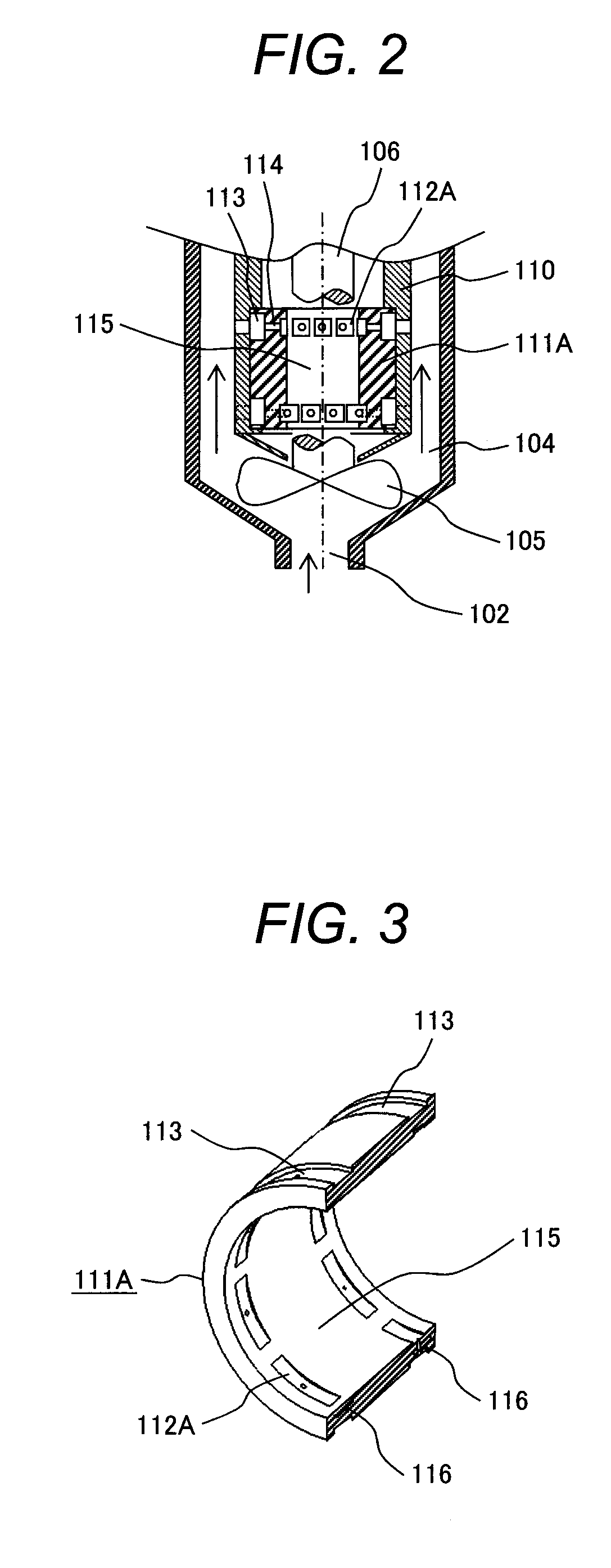
In a sliding bearing, load carrying capacity and bearing rigidity is increased without increasing a size of the bearing and the pressure of the fluid. The sliding bearing comprises a cylindrical-shaped sleeve supporting a rotatable shaft via fluid, and hydrostatic pressure pockets provided in the inner periphery of the sleeve. The hydrostatic pressure pockets constitute a plurality of rows of circumferentially disposed hydrostatic pressure pockets via orifices. At least one of the hydrostatic pressure pocket rows is arranged adjacently to each of both end portions of the inner periphery of the sleeve. And a circular cylindrical inner peripheral surface region without the hydrostatic pressure pockets is provided at a center portion of the sleeve. A width of the circular cylindrical inner peripheral surface region provided in the axial direction of the shaft is made wider than a sum of widths of the hydrostatic pressure pocket rows.

Description

CLAIM OF PRIORITY[0001]The present application claims priority from Japanese application serial No. 2011-271887 filed on Dec. 13, 2011, the content of which is hereby incorporated by reference into this applicationBACKGROUND OF THE INVENTION[0002]1. Field of the Invention[0003]The present invention relates to a sliding bearing provided with a hydrostatic pressure bearing structure in which high pressure fluid is supplied into a gap between the outer periphery of a shaft and the inner periphery of a sleeve from the outside and which supports rotational movement of the shaft, and a pump device provided with a mechanism which supports, through the sliding bearing, the rotational movement of the shaft connected to an impeller.[0004]2. Description of the Related Art[0005]As a large-sized pump device used in, for example, a circulative cooling system of a fast-breeder reactor, there has been generally used a mechanical-type vertical axial pump device in which an impeller attached to a lon...

Claims


Application Information

Patent Timeline
Patent Type & Authority Applications(United States)
IPC IPC(8): F04D29/047
CPCF04D29/0473F04D3/00F16C32/0685F04D29/0476F16C32/0651F04D13/08F16C2210/08
Inventor OYAMADA, TOMONAGAAIZAWA, KOUJIHAYASHI, MASAAKI
Owner HITACHI-GE NUCLEAR ENERGY LTD
Learn More