Method to Compensate for Errors in Time-of-Flight Range Cameras Caused by Multiple Reflections
- Summary
- Abstract
- Description
- Claims
- Application Information
AI Technical Summary
Benefits of technology
Problems solved by technology
Method used
Image
Examples
Embodiment Construction
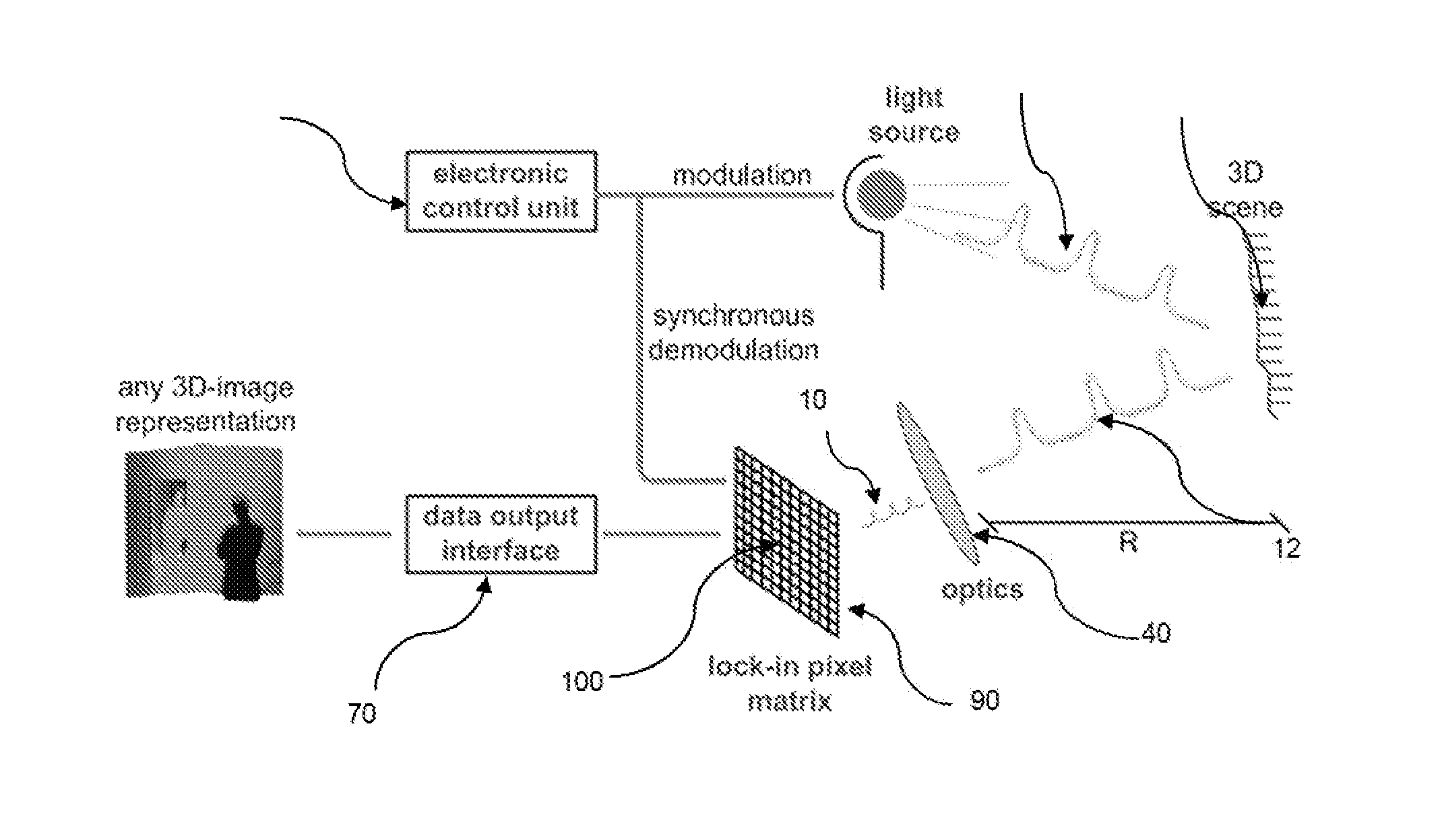
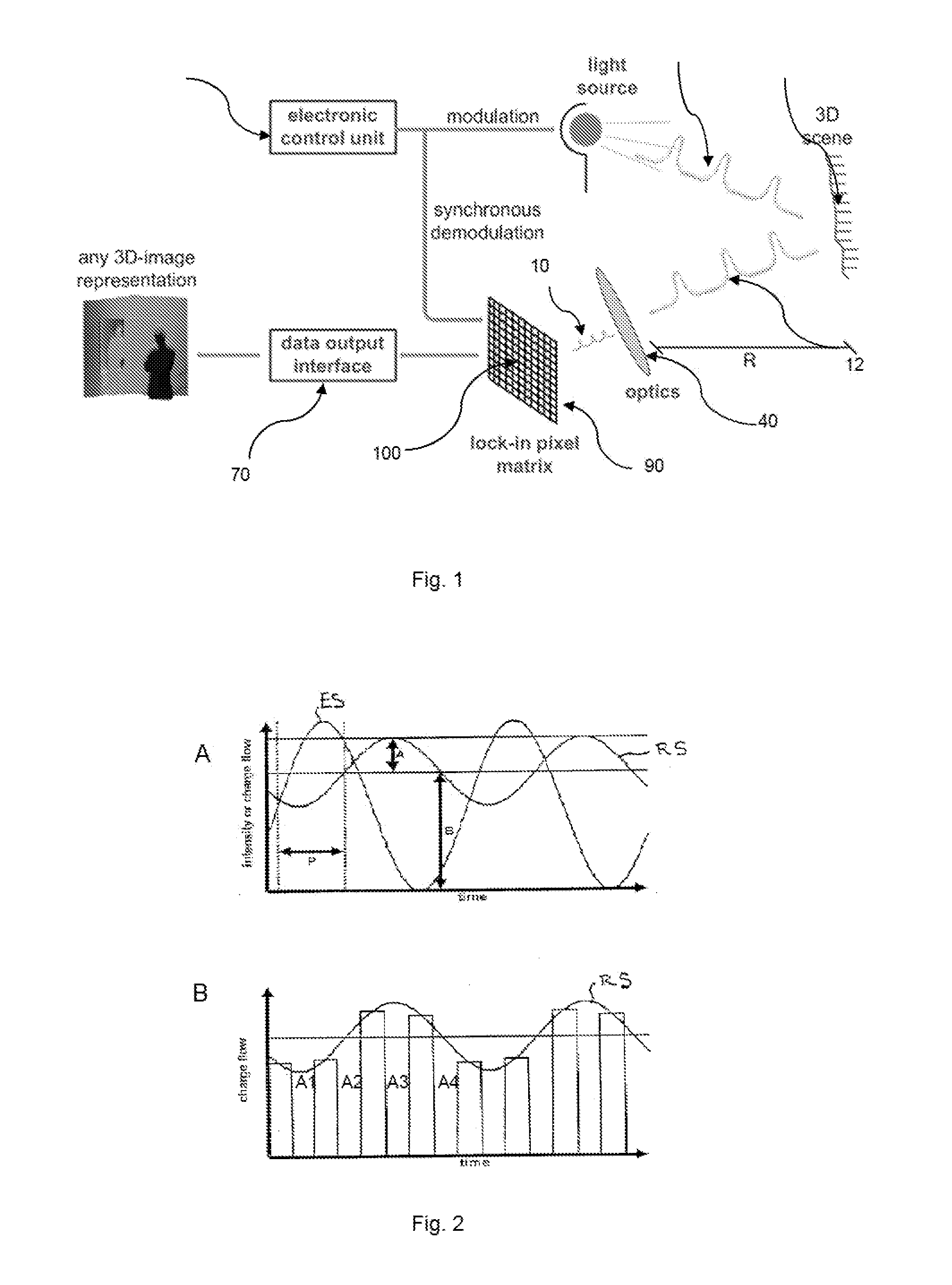
[0017]Modulated illumination light 11 from an illumination module or light source 20 is sent to the object 30 of a scene. A fraction of the total optical power sent out is reflected to the camera 12, through the optics 40 and detected by the 3D imaging sensor 90. The sensor 90 comprises a two dimensional pixel matrix of the demodulation pixels 100. Each pixel 100 is capable of demodulating the impinging light signal 10. An electronics. control unit 60 controls the timing of the illumination 20 and sensor 100. The demodulation values allow for each pixel to compute the time-of-flight, which, in turn, directly corresponds to the distance information of the corresponding point in the scene. The two-dimension gray scale image with the distance information is converted into a three-dimensional image by image processor IP. This can he displayed to a user via display D or used as a machine vision input.
[0018]The distance R for each pixel is calculated by
R=(c*TOF) / 2,
with c as light velocity...
PUM
 Abstract
Description
Claims
Application Information
 - R&D
- Intellectual Property
- Life Sciences
- Materials
- Tech Scout
- Unparalleled Data Quality
- Higher Quality Content
- 60% Fewer Hallucinations
Browse by: Latest US Patents, China's latest patents, Technical Efficacy Thesaurus, Application Domain, Technology Topic, Popular Technical Reports.
© 2025 PatSnap. All rights reserved.Legal|Privacy policy|Modern Slavery Act Transparency Statement|Sitemap|About US| Contact US: help@patsnap.com


