
Vehicle control device and vehicle control method

a technology of vehicle control and control device, which is applied in the direction of process and machine control, using reradiation, instruments, etc., can solve the problems of difficult to keep the inter-vehicle time between the preceding vehicle and the host vehicle during the deceleration of the preceding vehicle, and difficult to continue follow-up running

Active Publication Date: 2013-06-06
TOYOTA JIDOSHA KK
View PDF9 Cites 76 Cited by
  • Summary
  • Abstract
  • Description
  • Claims
  • Application Information

AI Technical Summary

Benefits of technology

The invention is a vehicle control device and method that can appropriately decelerate a vehicle during control of its running state by following a preceding vehicle. The device includes a system for acquiring information about the preceding vehicle and controlling the host vehicle based on this information. Additionally, the device includes a system for advancing the timing of deceleration of the host vehicle based on the deceleration jerk performance of the preceding vehicle. This allows for a smoother and more responsive control of the vehicle during this type of running control. The device can also detect and notify the driver of any communication breakdown that may occur during the control of the host vehicle. Overall, the invention improves the vehicle's control and stability during running and ensures a safe driving experience.

Problems solved by technology

However, the braking response characteristic at the time of braking may significantly vary depending on the type of a vehicle, and, when a variation in the deceleration of a preceding vehicle is larger than a variation in the deceleration of the host vehicle, it is difficult to keep the inter-vehicle time between the preceding vehicle and the host vehicle during deceleration of the preceding vehicle.
In this case, there has been a case where it is difficult to continue follow-up running.

Method used


Image

  • Vehicle control device and vehicle control method
  • Vehicle control device and vehicle control method
  • Vehicle control device and vehicle control method

Examples


embodiment

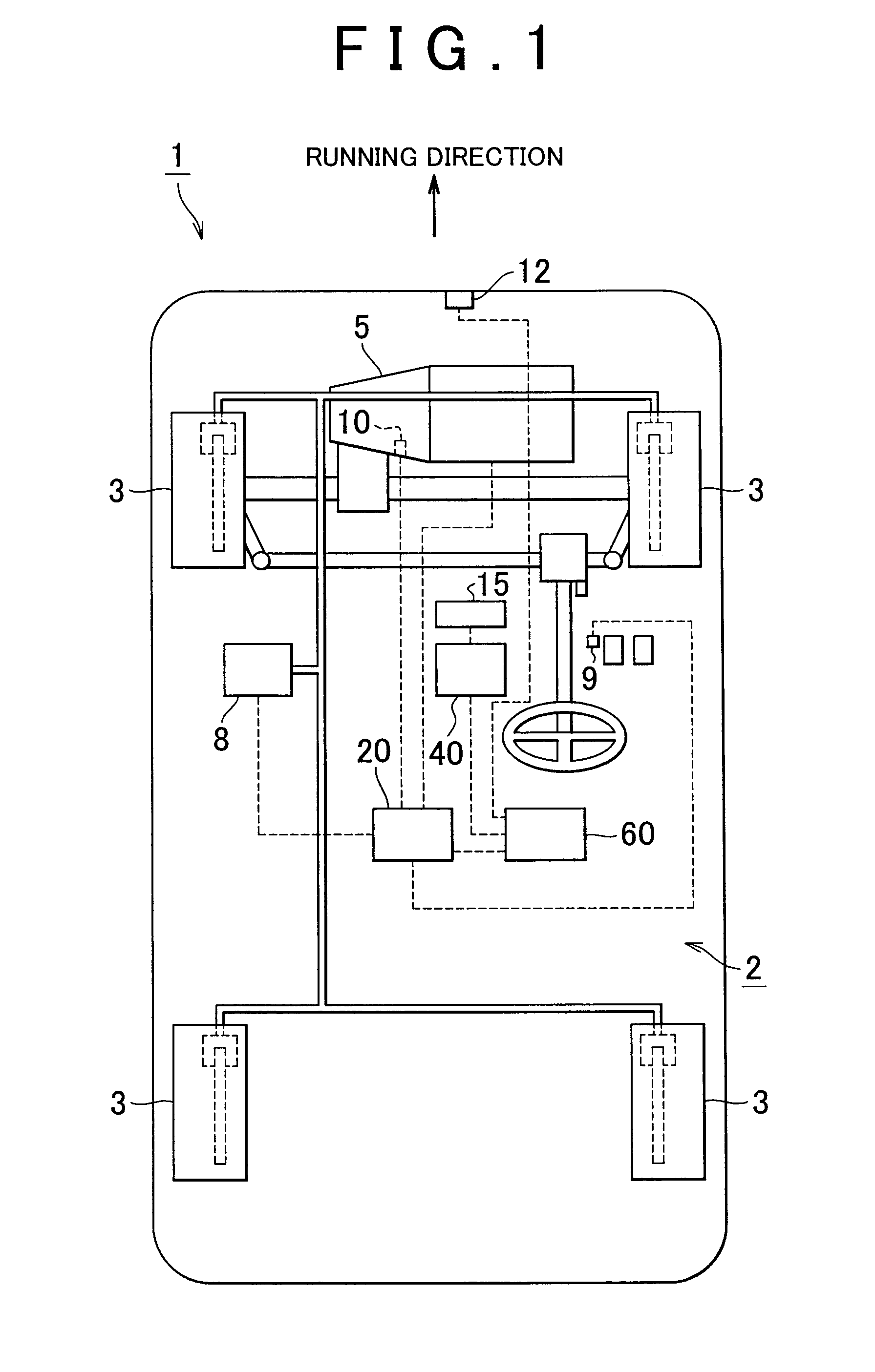
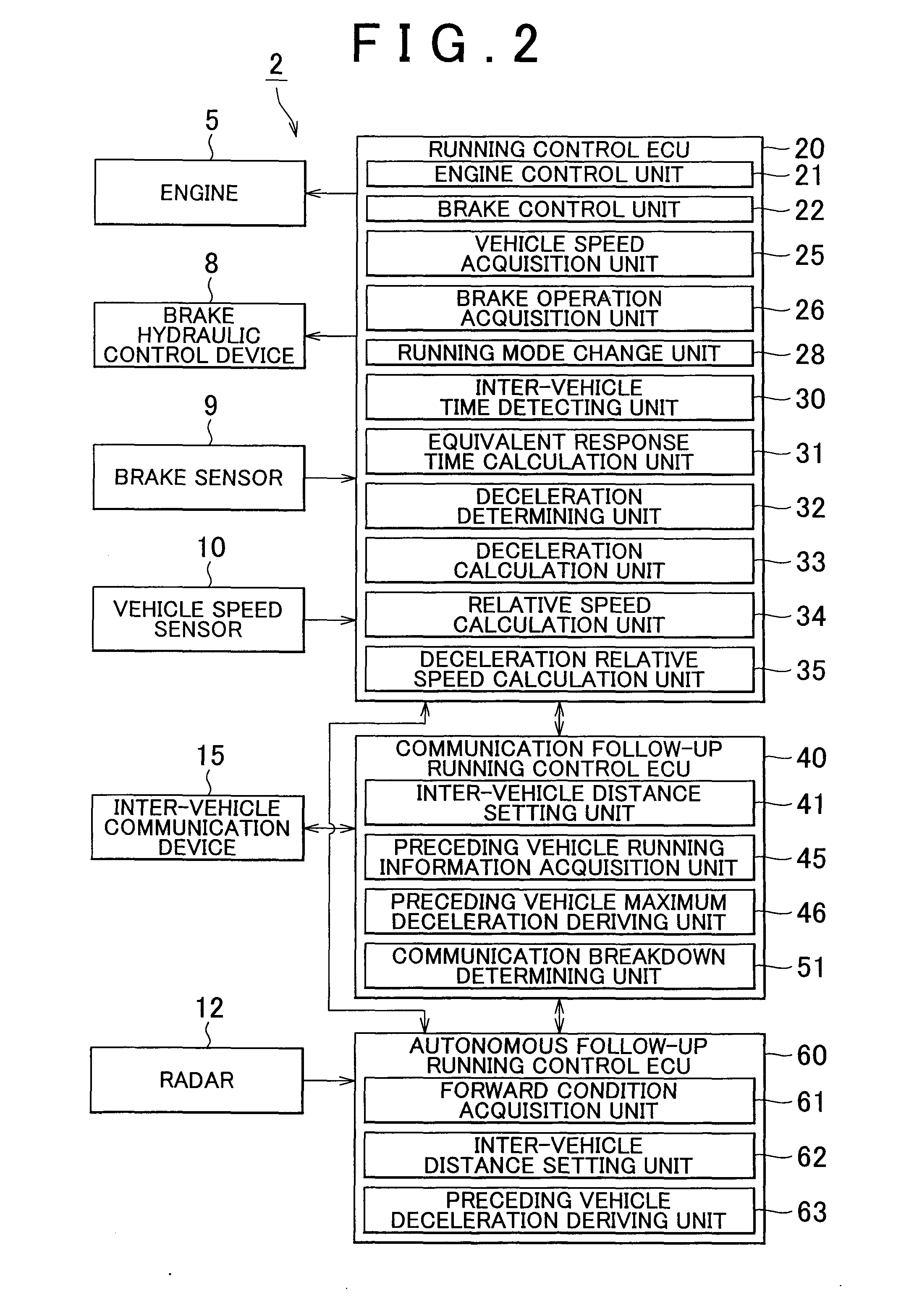
[0034]FIG. 1 is a schematic view of a vehicle provided with the vehicle control device according to the embodiment of the invention. The vehicle 1 provided with the vehicle control device 2 according to the embodiment is equipped with an engine 5, which is an internal combustion engine, as a power source. The vehicle 1 is able to run in such a manner that power generated by the engine 5 is transmitted to wheels 3 via a driving device, such as an automatic transmission (not shown). In addition, the vehicle 1 includes a brake device (not shown) and a brake hydraulic control device 8. The brake device is a braking device that brakes the wheels 3 to brake the moving vehicle 1. The brake hydraulic control device 8 controls hydraulic pressure for activating the brake device. In addition, a vehicle speed sensor 10 is provided for the driving device. The vehicle speed sensor 10 is a vehicle speed detecting device that detects a rotational speed at the time when the power of the engine 5 is ...


PUM


Abstract

Vehicle control includes: acquiring running information of a preceding vehicle that runs ahead of a host vehicle; controlling a running state of the host vehicle on the basis of the acquired running information; acquiring deceleration jerk information of the preceding vehicle; and changing a deceleration start timing, at which the host vehicle is decelerated in response to deceleration of the preceding vehicle, on the basis of the deceleration jerk information of the preceding vehicle. Alternatively, vehicle control includes: acquiring deceleration jerk information of a preceding vehicle that runs ahead of a host vehicle; and changing an inter-vehicle time or inter-vehicle distance between the preceding vehicle and the host vehicle on the basis of the deceleration jerk information of the preceding vehicle.

Description

BACKGROUND OF THE INVENTION[0001]1. Field of the Invention[0002]The invention relates to a vehicle control device and a vehicle control method.[0003]2. Description of Related Art[0004]In recent vehicles, a control device that automatically executes control during running of the vehicle has been developed in order to improve ease of driving during running of the vehicle, reduce a burden on driver's driving operation and further improve safety during running of the vehicle.[0005]For example, in a vehicle rear-end collision prevention system described in Japanese Patent Application Publication No. 9-27100 (JP-A-9-27100), a vehicle that runs ahead (preceding vehicle) is extracted from a captured image ahead of a host vehicle and, when there is a possibility that the host vehicle hits the rear end of the preceding vehicle, automatic braking is performed. In addition, when it is determined whether there is a possibility that the host vehicle hits the rear end of a preceding vehicle, the s...

Claims


Application Information

Patent Timeline
IPC IPC(8): B60K31/00G01S13/931
CPCB60K31/0008B60K31/00B60W2550/10B60W2550/306G01S13/931G01S2013/9325G01S2013/9346G01S2013/935G01S2013/9353G01S2013/936G08G1/22B60K2310/28B60W30/16B60K2031/0033B60W2550/302B60K2310/264B60K2310/262G01S2013/9319G01S2013/93185G01S2013/9316G01S2013/932B60W2554/804B60W2554/4041B60W2554/00B60W2554/4042B60W2554/802
Inventor SHIDA, MITSUHISA
Owner TOYOTA JIDOSHA KK
Learn More