
Trackless dark ride vehicle, system, and method

Inactive Publication Date: 2013-06-06
OCEANEERING INTERNATIONAL
View PDF12 Cites 20 Cited by
  • Summary
  • Abstract
  • Description
  • Claims
  • Application Information

AI Technical Summary

Benefits of technology

The invention is about a vehicle that has a chassis and two propulation wheels. It also has a slew bearing with a fixed side and a rotatable gear, a motor to move the gear, and a platform that can rotate with the chassis. The vehicle also has seating with a front and back side, and the front side can be adjusted to point in any direction. This allows for flexibility and versatility in the vehicle's movement.

Problems solved by technology

These vehicles were loud, due to the metal-on-metal sound of wheels on tracks.
Rides making use of these vehicles were not amenable to changes, because of the difficulty of removing, reconfiguring, and reinstalling the tracks.
Additionally, these vehicles were not self-powered.
The movement of the rope, chain, or cable also caused undesirable noise.
Moreover, the mere existence of the rope, chain, or cable posed a physical threat (due to tripping or entanglement) to any person departing the safety of the ride vehicle and to the amusement ride operators themselves.
Electrical vehicles of this type presented the serious danger of electrocution of a patron if the patron left the ride vehicle and stumbled on an electrified third-rail.
Additionally, electrical vehicles of this type were still bound to a track and all of the problems related thereto.
Electrical vehicles of this type also present the serious danger of electrocution of a patron if the patron made contact with an improperly insulated pole (supporting the contact scraping the electrified grid above the ride) and ground at the same time.
These vehicles moreover typically presented the problem of a lack of safety features that could disable one or all of the vehicles in the ride if a patron was to leave a vehicle during the ride.
Similar lack of safety features were present in electrified vehicles running on tracks.
This type of ride presents two problems in the field of ride vehicles.
First, the locomotion of large battery-operated vehicles consumes a great deal of energy.
Storage of a large amount of energy requires many rechargeable-type batteries.
Second, vehicles that use guide-wires embedded in a floor, similar to vehicles that ride on tracks, are not amenable to changes in the configuration of the vehicle's path of travel, because of the difficulty of removing, reconfiguring, and reinstalling the wires.
Moreover, just like tracks, a vehicle following a guide wire must stay on the guide wire, therefore, it must eventually return to the point from which it began its journey and cannot easily, if at all, follow a path that crosses over itself.
Still other problems confront designers of modern amusement rides.
Patrons are no longer satisfied with simply moving through a ride while being maintained in one plane of travel.
Motion assemblies exist that provide these four degrees of motion to ride patrons; however, due to the very large consumption of power (necessitated by moving a platform that supports the weight of a given number of patrons through space in these directions), known four degree of freedom motion assemblies are coupled to fixed supplies of electrical power.
This limits the mounting of prior art motion assemblies either to fixed locations or to mounts on tracks that use a “third rail” type of electrical connection to supply power to the motion assembly.
The former situation is problematic at least because patrons are usually confined to a single room (which may move in yaw, roll, pitch, and heave) while images are projected on the walls within the room.
The latter situation is problematic at least because patrons face all the same issues faced by patrons of older ride vehicles that were confined to riding on tracks; additionally there is the danger of electrocution if a patron was to leave the ride vehicle and stumble on the electrified third-rail.
Still other problems exist with respect to the motions of prior art vehicles.
The recharging of battery operated vehicles is also problematic.
Rapid charging was not possible, as batteries would overheat if too much charge were pushed into them too quickly.

Method used


Image

  • Trackless dark ride vehicle, system, and method
  • Trackless dark ride vehicle, system, and method
  • Trackless dark ride vehicle, system, and method

Examples


Embodiment Construction

[0028]It is to be understood that both the foregoing general description and the following detailed description are exemplary. As such, the descriptions herein are not intended to limit the scope of the present invention. Instead, the scope of the present invention is governed by the scope of the appended claims.

[0029]The ride vehicle described herein may be comprised of three assemblies: the transport assembly, the motion assembly, and the passenger assembly. The motion assembly mounts on top of the transport assembly. The passenger assembly mounts on top of the motion assemblies. The invention is not limited to this configuration. Each of the three assemblies will be described in order below.

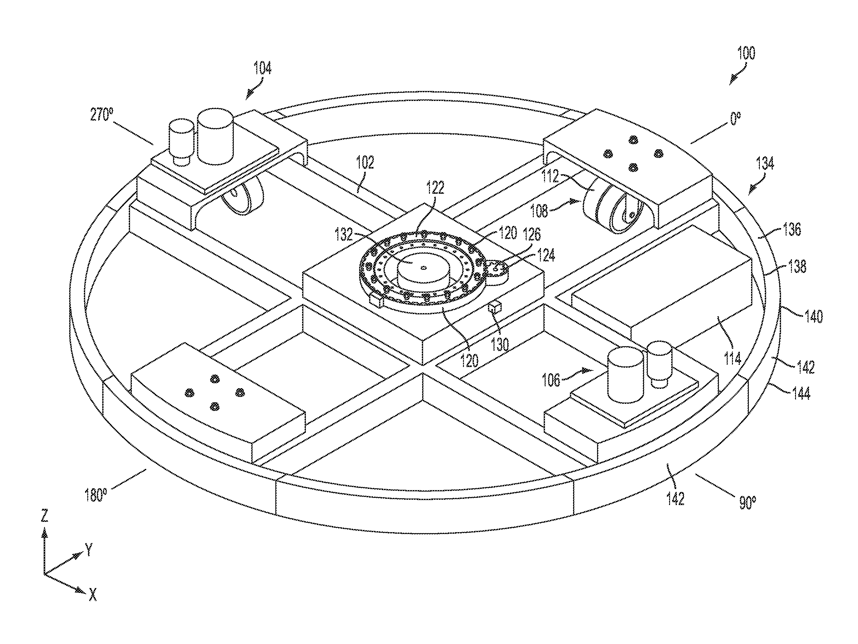
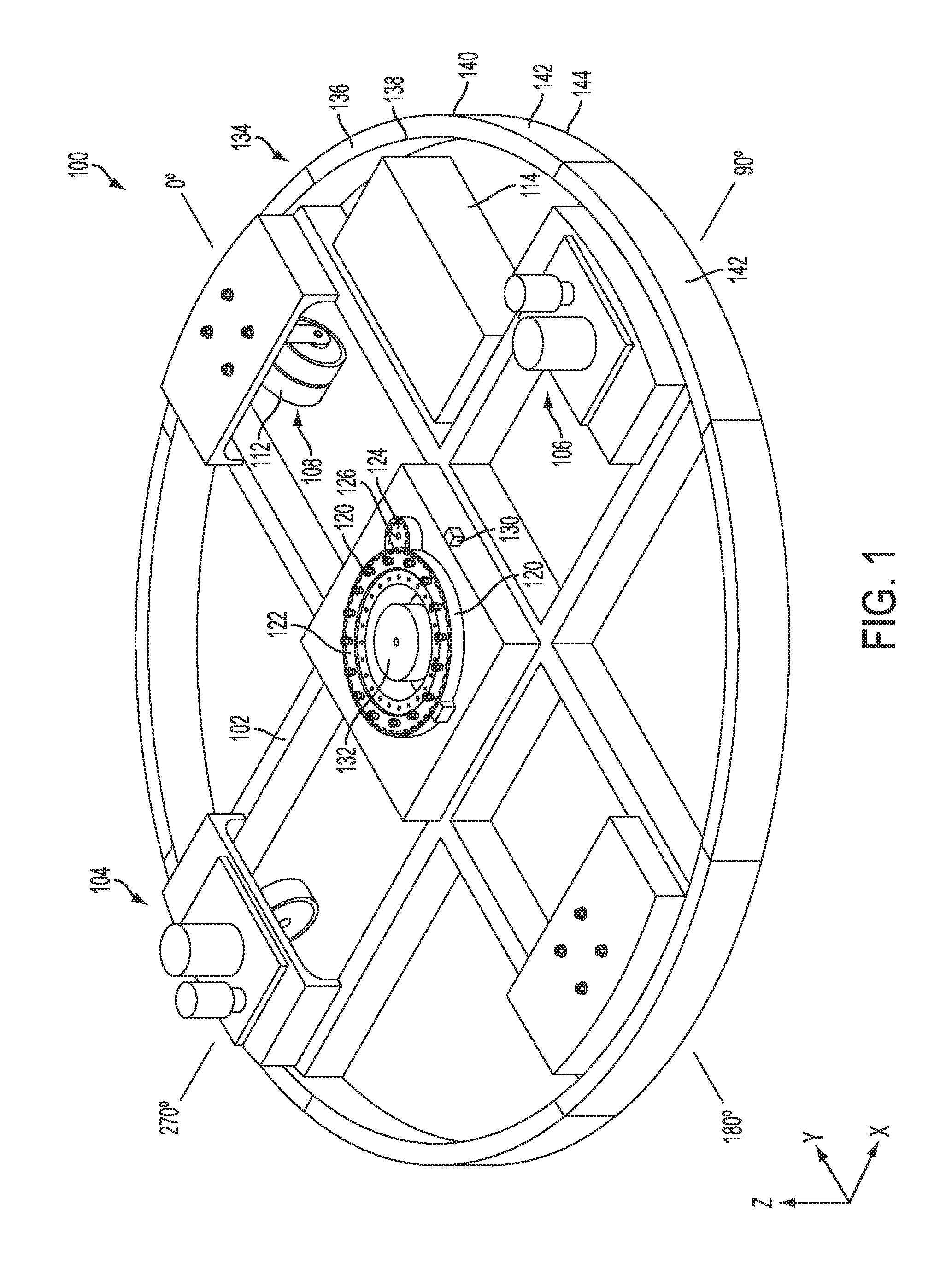
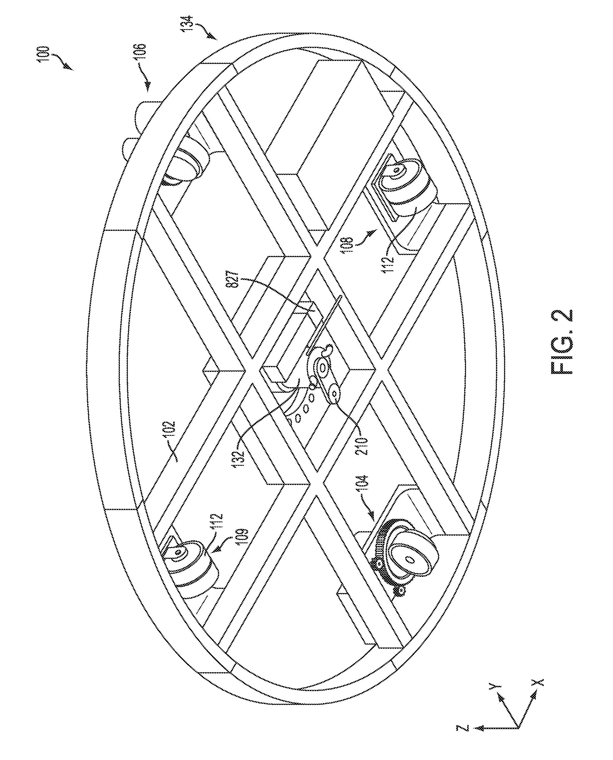
[0030]FIG. 1 is a top-side isometric view of a transport assembly of a vehicle 100, in accordance with an embodiment of the invention. FIG. 2 is a bottom-side isometric view of the transport assembly of the vehicle of FIG. 1. The transport assembly 100 is a structural frame of the ride vehicle...


PUM


Abstract

A motion assembly that produces pitch and roll motions includes lower and upper plates. A pivotable coupling having upper and lower shafts extending from its center is coupled between the upper and lower plates. At least two linear actuators are coupled between the plates. Extension and retraction of the actuators pivots the upper plate about the pivotable coupling relative to the lower plate. A vehicle includes two steerable propulsion wheels coupled to a chassis. A lower plate of a pitch and roll assembly, similar to that just described, couples to the chassis via a slew bearing. Seating is coupled to the upper plate. The seating rotates with respect to the chassis via controlled rotation of the slew bearing with reference to the chassis. The seating can be rotated to point in any direction with respect to the chassis regardless of the direction the steerable propulsion wheels move the chassis.

Description

[0001]This application claims priority from U.S. Provisional Application No. 61 / 484,942, filed on May 11, 2011, the content of which is hereby incorporated by reference for all purposes as if fully presented herein.FIELD OF THE INVENTION[0002]The present invention is directed to multi-passenger vehicles used in amusement park rides. More specifically, the vehicle is battery operated and includes features permitting passengers to experience motion with three degrees of freedom (yaw, pitch, and roll) while simultaneously being propelled along a preprogrammed route, which is autonomously traveled by the vehicle without use of a mechanical track or wire stretched along the route.BACKGROUND OF THE INVENTION[0003]Vehicles for amusement park rides have existed for a long time. Earliest vehicles rode on tracks. These vehicles were loud, due to the metal-on-metal sound of wheels on tracks. Rides making use of these vehicles were not amenable to changes, because of the difficulty of removing,...

Claims


Application Information

Patent Timeline
IPC IPC(8): B62D5/04B62D3/00B62D7/06F16H21/54
CPCB62D3/00B62D5/04Y10T74/18888F16H21/54A63G25/00B62D7/06A63G7/00A63G21/08A63G31/08B62D5/0421G09B9/04G09B9/12B62D3/02F16M2200/048G09B9/02F16M11/18F16M11/126A63G31/16
Inventor FOSTER, SAMUEL T.BOSHEARS, MICHAEL WAYNEGRANT, ANDREWHASS, FRANK PETERJENNINGS, CLIFFORD ALLENKING, ERIC AUTHURKROSLOWITZ, KENNETH THOMASMALGHAN, SUHAS SUBHASCHANDRASYWAK, STEPHEN A.
Owner OCEANEERING INTERNATIONAL
Learn More