Elastic joint body
a joint body and elastic technology, applied in the field of elastic joint bodies, can solve the problems of reducing the lifespan, affecting and affecting the function of the joint body, so as to ensure the functioning of the joint body and increase the life of the joint body
- Summary
- Abstract
- Description
- Claims
- Application Information
AI Technical Summary
Benefits of technology
Problems solved by technology
Method used
Image
Examples
first embodiment
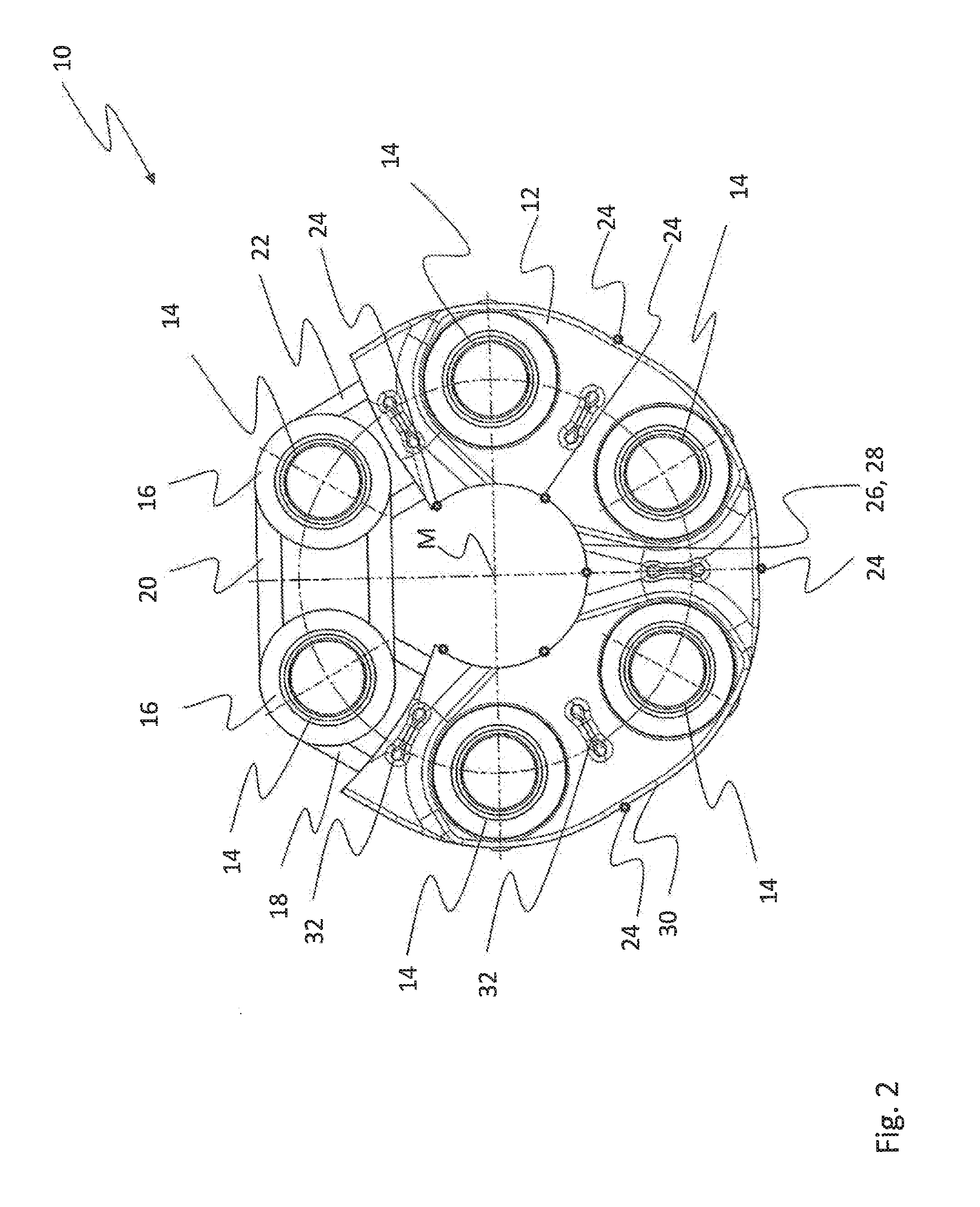
[0035]FIG. 1 shows a perspective view of the elastic joint body 10 according to the invention, with six bushes 14 which are sheathed by a rubbery-elastic sheathing 12. The bushes 14 are arranged at predetermined angular intervals on the joint body 10 in the peripheral direction with respect to a central axis M. In that region of the joint body 10 acts cording to FIG. 1 which is represented in cut-away form in the drawing, there can be seen the flange elements 16 on the bushes 14, which elements are provided for axially supporting the sets of loops 18, 20 and 22. Both the flanged bushes 16 and the sets of loops 18, 20 and 22 are sheathed by the rubbery-elastic sheathing 12.
[0036]It can also be seen from FIG. 1 that an individual bush 14 is wrapped around, in each case, by a number of sets of loops 18, 20 or 20, 22. Under these circumstances, provision may be made for the sets of loops 18, 22 to be stressed by a tensile force when the joint body 10 is in the installed condition in a s...
second embodiment
[0043]FIG. 3 shows a perspective view of a joint body 110 according to the invention.
[0044]The joint body 110 corresponds, to a large extent, to the joint body 10 described with reference to FIGS. 1 and 2, but in the joint body 110, the gate lands 124 are arranged in line with the axes of the bushes 114.
[0045]It can also be seen in FIG. 3 that, according to this embodiment, the axial gate lands 124 span only a partial region of the axial extension of the joint body 110. Accordingly, the axial gate lands 124 do not reach as far as the edges of the joint body 110, but extend in a central region of the axial extension of the latter.
third embodiment
[0046]FIG. 4 shows a perspective view of a joint body 210 according to the invention.
[0047]The gate lands 224 of the joint body 210 extend in the peripheral direction of the latter. In this instance, the gate lands 224 run along the inner peripheral face 226 of the central aperture 228 or along the outer peripheral face 230 of the joint body 210. In other words, the gate lands 224 run completely round the inner peripheral face 226 and the outer peripheral face 230, the gate lands 224 according to this embodiment being provided in a central region of the axial extension of the joint body 210.
[0048]However, the gate lands 224 do not have to be arranged on the inner peripheral face 226 and on the outer peripheral face 230. It is sufficient if the gate lands 224 that extend in the peripheral direction are arranged either on the inner peripheral face 226 of the central aperture 228 or on the outer peripheral face 230 of the joint body 210.
PUM
| Property | Measurement | Unit |
|---|---|---|
| elastic | aaaaa | aaaaa |
| elastomeric | aaaaa | aaaaa |
| rubbery-elastic | aaaaa | aaaaa |
Abstract
Description
Claims
Application Information
 - R&D
- Intellectual Property
- Life Sciences
- Materials
- Tech Scout
- Unparalleled Data Quality
- Higher Quality Content
- 60% Fewer Hallucinations
Browse by: Latest US Patents, China's latest patents, Technical Efficacy Thesaurus, Application Domain, Technology Topic, Popular Technical Reports.
© 2025 PatSnap. All rights reserved.Legal|Privacy policy|Modern Slavery Act Transparency Statement|Sitemap|About US| Contact US: help@patsnap.com


