
Method and Apparatus for Wireless Transmission of Data Packets

Active Publication Date: 2013-05-30
SIEMENS AG
View PDF0 Cites 14 Cited by
  • Summary
  • Abstract
  • Description
  • Claims
  • Application Information

AI Technical Summary

Benefits of technology

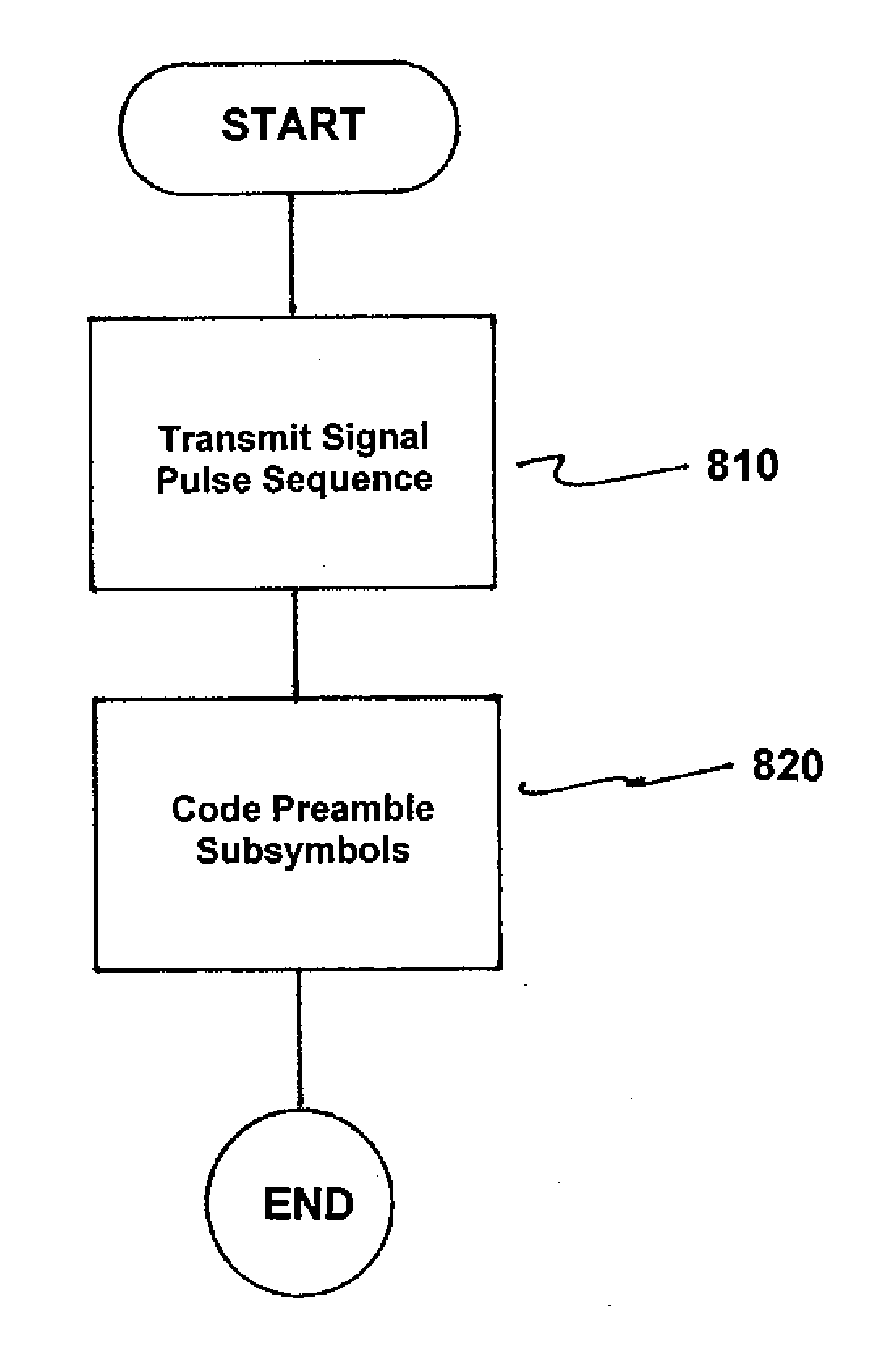
The present invention provides a method and apparatus for wireless transmission of data packets between network nodes in a control network with low data packet loss rate. This is achieved by introducing an additional operating mode that simplifies recognition of the preamble and reducing data packet loss rate. The method includes coding each preamble subsymbol of a preamble symbol in the preamble by the phase angle of a transmitted single signal pulse and transmitting a signal pulse sequence for coding the preamble subsymbol instead of a single signal pulse to increase signal recognition performance for the preamble in the data packet.

Problems solved by technology

In this case, the provision of high data transmission reliability represents a technical challenge because the majority of conventional measures used to increase reliability during data transmission increase latency.
Industrial production plants with machines controlled by a control network constitute a difficult environment for wireless communication via radio interfaces.
Production plants or industrial production cells with machines are associated with metal surfaces that interrupt or reflect the data transmission signals so that a relatively high level of electromagnetic noise is present.
The above-named problems mean conventional radio network technologies, such as Bluetooth or Institute of Electrical and Electronic Engineers (IEEE) standard 802.15.4 are not really suitable for control networks, i.e. in industrial production environments or factory automation.
However, it has been found that data packet transmission according to IEEE standard 802.15.4 results in a high data packet loss rate.
Here, the high packet loss rates are above all due to incorrectly recognized preambles in the headers of the data packets.

Method used


Image

  • Method and Apparatus for Wireless Transmission of Data Packets
  • Method and Apparatus for Wireless Transmission of Data Packets
  • Method and Apparatus for Wireless Transmission of Data Packets

Examples


Embodiment Construction

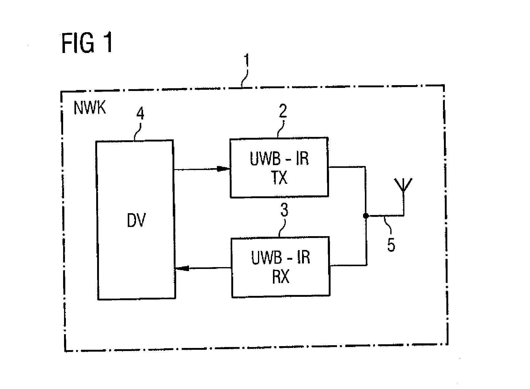
[0042]With the wireless control network in accordance with the invention, data packets DP are transmitted between network nodes 1. As shown in FIG. 1, in the exemplary embodiment depicted, a network node 1 of the control network comprises a transmitting device 2 and a receiving device 3 which are each connected to a data processing device 4, such as a CPU or microprocessor. The transmitting device 2 and the receiving device 3 are also connected to a transmitting and receiving antenna 5. The network nodes 1 use the transmitting and receiving antenna 5 to communicate via a wireless interface or radio interface with further network nodes in the wireless control network.

[0043]In one contemplated embodiment, the transmitting device 2 and the receiving device 3 each have separate antennas, i.e., the transmitting device 2 is connected to a transmitting antenna and the receiving device 3 is connected to a receiving antenna. The network node 1 can comprise further devices or switching parts,...


PUM


Abstract

Method for wire-free transmission of data packets between network nodes in a control network, wherein the data packets each have a preamble for synchronization consisting of a predetermined number of preamble symbols, and wherein during a first operating mode, each preamble-subsymbol of a preamble symbol in the preamble is coded by the phase angle of a transmitted single signal pulse, during a second operating mode to increase the signal recognition performance, for the preamble which is transmitted in the data packet, a signal pulse sequence for coding the preamble-subsymbol is transmitted instead of a single signal pulse, where the single signal pulse within the signal pulse sequence is transmitted repeatedly.

Description

CROSS-REFERENCE TO RELATED APPLICATIONS[0001]This is a U.S. national stage of application No. PCT / EP2011 / 053020 filed 1 Mar. 2011. Priority is claimed on German Application No. 10 2010 009 678.4 filed 1 Mar. 2010, the content of which is incorporated herein by reference in its entirety.BACKGROUND OF THE INVENTION[0002]1. Field of the Invention[0003]The invention relates to data packet transmission and, more particularly, to a method and apparatus for Wireless transmission of data packets between network nodes in a control network.[0004]2. Description of the Related Art[0005]During wireless communication between network nodes in a control network, for example, for controlling machines, data packets are transmitted via radio interfaces. Wireless communication for controlling machines requires, on the one hand, very low latencies and, on the other, very high data transmission reliability. It is also necessary for the control network to be able to co-exist with other wireless networks, ...

Claims


Application Information

Patent Timeline
IPC IPC(8): H04W40/00
CPCH04W40/00H04B1/7183H04B1/7163H04B10/524H04B14/023
Inventor HUND, JOHANNESHEINRICH, ANDREASHUCKENHOLZ, STEPHANSCHWINGENSCHLOGL, CHRISTIAN
Owner SIEMENS AG
Learn More