
Storage system, control program and storage system control method

a storage system and control program technology, applied in the field of storage system enhancement, can solve the problems of reducing the system performance, increasing the cost of a large number of required lms, etc., and achieve the effect of improving enhancing the processing performance of the storage system, and improving the probability of hitting the control information which is accessed frequently

Active Publication Date: 2013-05-23
HITACHI LTD
View PDF0 Cites 1 Cited by
  • Summary
  • Abstract
  • Description
  • Claims
  • Application Information

AI Technical Summary

Benefits of technology

[0006]In a storage system having multiple processor as disclosed in Patent Document 1, an access to the SM has a longer access latency than an access to a local memory (LM) directly connecting to the corresponding processor because the SM is accessed over a network among the processors. This may reduce the performance of the system when the number of accesses to the SM increases.
[0008]Accordingly, it is an object of the present invention to provide a storage system having multiple processors with much higher performance by enhancing the access performance to control information in a shared memory, without requiring a large number of local memories.
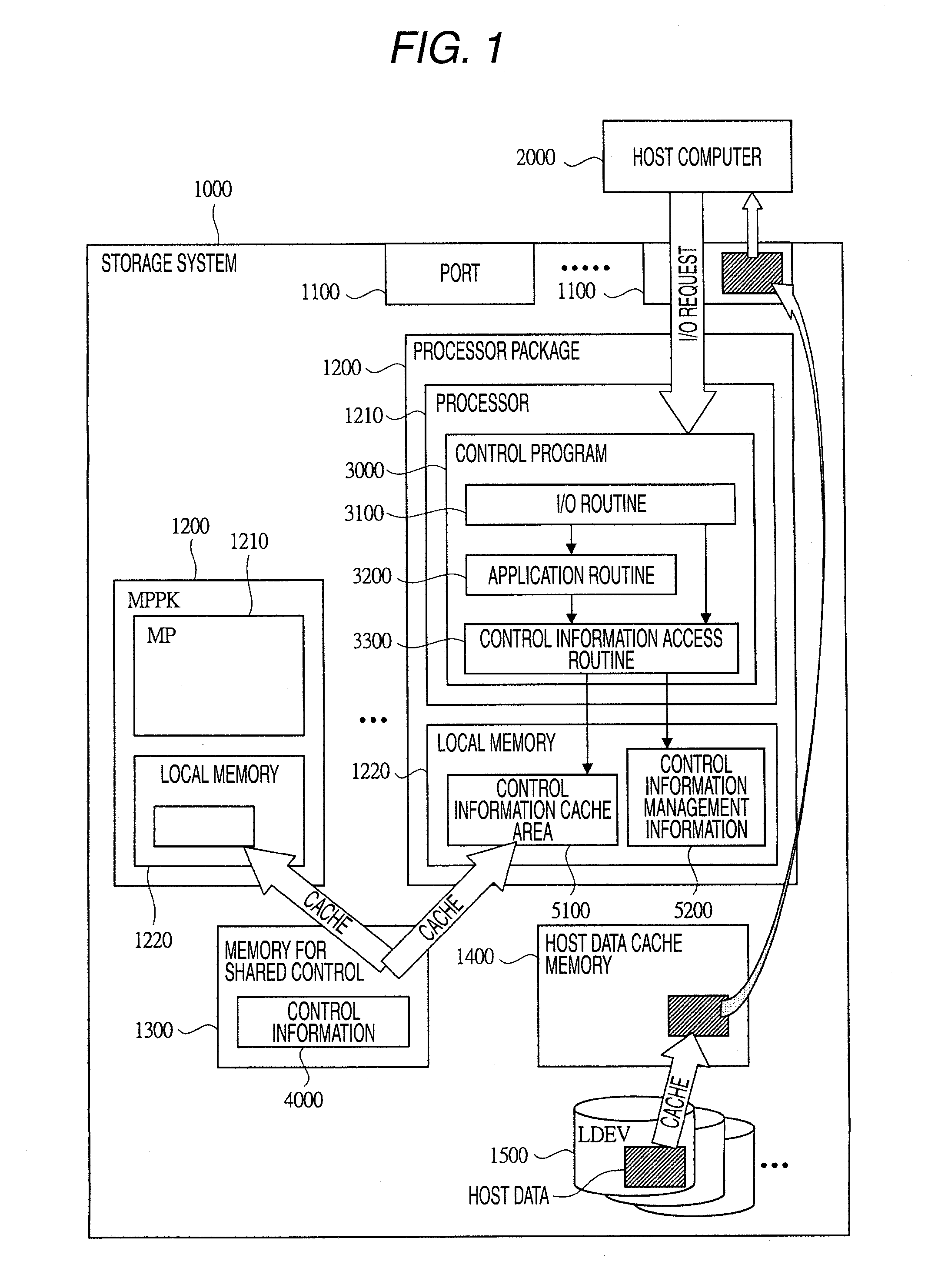
[0013]In a representative embodiment of the invention, the processing performance of a storage system can be enhanced by the access to a part of control information cached by a control program that operates in a processor in referring to the control information in an SM. The LM hit probability on control information which is accessed frequently can be improved, which thus improves the processing performance of a storage system, by cashing the control information on a type-by-type basis in different storage areas in an LM.

Problems solved by technology

This may reduce the performance of the system when the number of accesses to the SM increases.
However, it requires holding copies of the whole control information, the number of which is equal to the number of processors, and a large number of required LMs may increase the costs.

Method used


Image

  • Storage system, control program and storage system control method
  • Storage system, control program and storage system control method
  • Storage system, control program and storage system control method

Examples


first embodiment

[0063]The computer system which is a first embodiment of the invention will be described below.

[System Configuration]

[0064]FIG. 1 is a diagram showing an outline of a configuration example of the computer system which is this embodiment. The compute system of this embodiment includes a storage system 1000 and a host computer (or host) 2000.

[0065]The storage system 1000 includes one or more ports 1100 for communicating with the host 2000, one or more processor packages (MPPK: Micro Processor package) 1200, a memory for shared control (or shared memory: SM) 1300, a host data cache memory (or cache memory: CM) 1400, and one or more volumes (or Logical Device: LDEV) 1500. The LDEV 1500 has an LDEV number for uniquely identifying the LDEV 1500 by the storage system 1000.

[0066]The host 2000 transmits an I / O (or Input / Output) request to the storage system 1000 for writing or reading data to or from the storage system 1000. The I / O request may be an SCSI (Small Computer System Interface) co...

second embodiment

[0168]The computer system which is a second embodiment of the invention will be described below. This embodiment is an example in a case where the size of the storage area to cache the control information 4000 in the LM 1220 is changed dynamically in accordance with the configuration change in the storage system 1000. Because the outline of the system configuration, hardware configuration and so on are similar to those in the first embodiment, the repetitive description thereon will be omitted.

[Control Program Configuration]

[0169]FIG. 20 is a diagram showing a configuration example of a control program 3000 in the computer system of this embodiment. It is different from the configuration example of the control program 3000 in the first embodiment, which is described with reference to FIG. 4, in that it further includes a storage area setting / changing routine 3500. The storage area setting / changing routine 3500 provides a function for dynamically changing the size of the storage area...

third embodiment

[0219]The computer system which is a third embodiment of the invention will be described below. This embodiment is an example in a case where management information on control information pieces 4000 is displayed on a management terminal 2100. Because the outline of the system configuration, hardware configuration and so on are similar to those in the first embodiment, the repetitive description thereon will be omitted.

[0220]FIG. 29 is a diagram showing a configuration example of a control program 3000 in the computer system of this embodiment. It is different from the configuration example of the control program 3000 of the second embodiment, which has been described with reference to FIG. 20, in that it further includes a management information display routine 3600. The management information display routine 3600 provides functions of receiving a management information display request transmitted by the management terminal 2100, obtaining management information on control informat...


PUM


Abstract

There is provided a storage system including one or more LDEVs, one or more processors, a local memory or memories corresponding to the processor or processors, and a shared memory, which is shared by the processors, wherein control information on I / O processing or application processing is stored in the shared memory, and the processor caches a part of the control information in different storage areas on a type-by-type basis in the local memory or memories corresponding to the processor or processors in referring to the control information stored in the shared memory.

Description

CROSS REFERENCE TO RELATED APPLICATIONS[0001]This application is a continuation of U.S. Appln. Ser. No. 12 / 338,238, filed Dec. 18, 2008 and which application relates to and claims priority from Japanese Patent Application No. 2008-253466, filed on Sep. 30, 2008, the entire disclosure of which is incorporated herein by reference.BACKGROUND OF THE INVENTION[0002]1. Field of the Invention[0003]The present invention relates to enhancement of performance of a storage system, and it particularly relates to an effective technology applicable to a storage system that has multiple processors and controls disk apparatus by using control information in a shared memory, a control program therefor and a storage system control method.[0004]2. Description of the Related Art[0005]As a high-performance and highly reliable storage system, Japanese Patent Publication No. 3264465 (Patent Document 1) discloses a storage system that operates by distributing routines over multiple processors and storing c...

Claims


Application Information

Patent Timeline
Patent Type & Authority Applications(United States)
IPC IPC(8): G06F12/08
CPCG06F3/061G06F3/0656G06F3/0658G06F12/084G06F12/0875G06F2212/3035G06F2212/466G06F3/0689
Inventor ITO, SHINTAROSHIMOZONO, NORIO
Owner HITACHI LTD
Learn More