Lockable attachment and styptic device including same

Inactive Publication Date: 2013-05-23
BENRIKAL SERVICES
View PDF2 Cites 7 Cited by
  • Summary
  • Abstract
  • Description
  • Claims
  • Application Information

AI Technical Summary

Benefits of technology

The patent describes a styptic device for stopping blood flow through percutaneous punctures. The device includes a flexible element and a safety catch. The flexible element has serrated surfaces and is locked in a tensioned state using the safety catch. The safety catch prevents deformation of the tongue and is easily detached when needed. The styptic device is comfortable for the patient and can be easily manufactured and used. The technical effect of this device is to provide a reliable and efficient tool for medical procedures that reduces the risk of bleeding.

Problems solved by technology

Also, during the procedure, the catheter may be twisted or otherwise manipulated as it is advanced to the treatment site, hence potentially causing a further enlargement of the puncture.
Such procedures hence unavoidably present the problem of stopping the bleeding at the percutaneous puncture site after the procedure has been completed and after the instrument and any introducer sheaths used therewith have been removed.
First, the direct digital pressure application procedure constitutes an inefficient, if not wasteful, use of medical professional services. For example, in the case of punctures into relatively high pressure vessels, such as into the femoral artery or superficial femoral arteries, the pressure may have to be applied for as long as forty-five minutes for haemostasis to occur.
Second, the application of digital pressure over a relatively long period of time may result in fatigue, numbness, stiffness and / or pain occurring in the fingers, hands, wrists and / or forearms of the practitioner performing the procedure. Furthermore, repetition of the procedure over a period of time may cause repetitive-type stress injuries, such as carpal tunnel syndrome or the like.
Still furthermore, although the procedure is typically performed with gloves there exists a possibility that the glove could already have, or may develop, a tear, thereby allowing direct pressurized digital contact with potentially contaminating bodily fluids.
Third, it is often difficult for an individual to exert digital pressure of optimal magnitude, especially over a relatively long period of time.
Indeed, should the magnitude of the pressure be suboptimal, a bruise or haematoma may form at the entry site since internal bleeding of the punctured artery continues until clotting blocks the puncture.
On the contrary, should the applied pressure be too great, this may result in a substantial reduction, if not virtual arrest, of the flow of blood through the vessel.
This, in turn, may lead to thrombosis of the vessel with potentially serious complications.
Yet another drawback associated with the conventional digital application of pressure at the puncture site results from the fact that the instrument and any introducer sheath used therewith is typically completely withdrawn prior to the application of pressure at the puncture site.
This results in a brief, yet vigorous, free-flow of blood through the puncture site, which may obscure the exact location of the puncture momentarily leading to further blood loss.
Still furthermore, the conventional method of digital pressure application of the puncture site is sometimes considered uncomfortable for the patient and requires that the patient remain immobilized in the operating room, catheter lab, holding area or the like, hence using up valuable space.
However, such prior art devices suffer from numerous drawbacks.
Indeed, prior art device generally suffer from being unergonomical to the user and uncomfortable to the patient.
Prior art devices also suffer from being overall too complex, and, hence, relatively expensive and potentially unreliable.
There is in some of these prior art styptic device a risk that the tongue is inadvertently released, which could cause bleeding and other complications.

Method used


Image

  • Lockable attachment and styptic device including same
  • Lockable attachment and styptic device including same
  • Lockable attachment and styptic device including same

Examples


Embodiment Construction

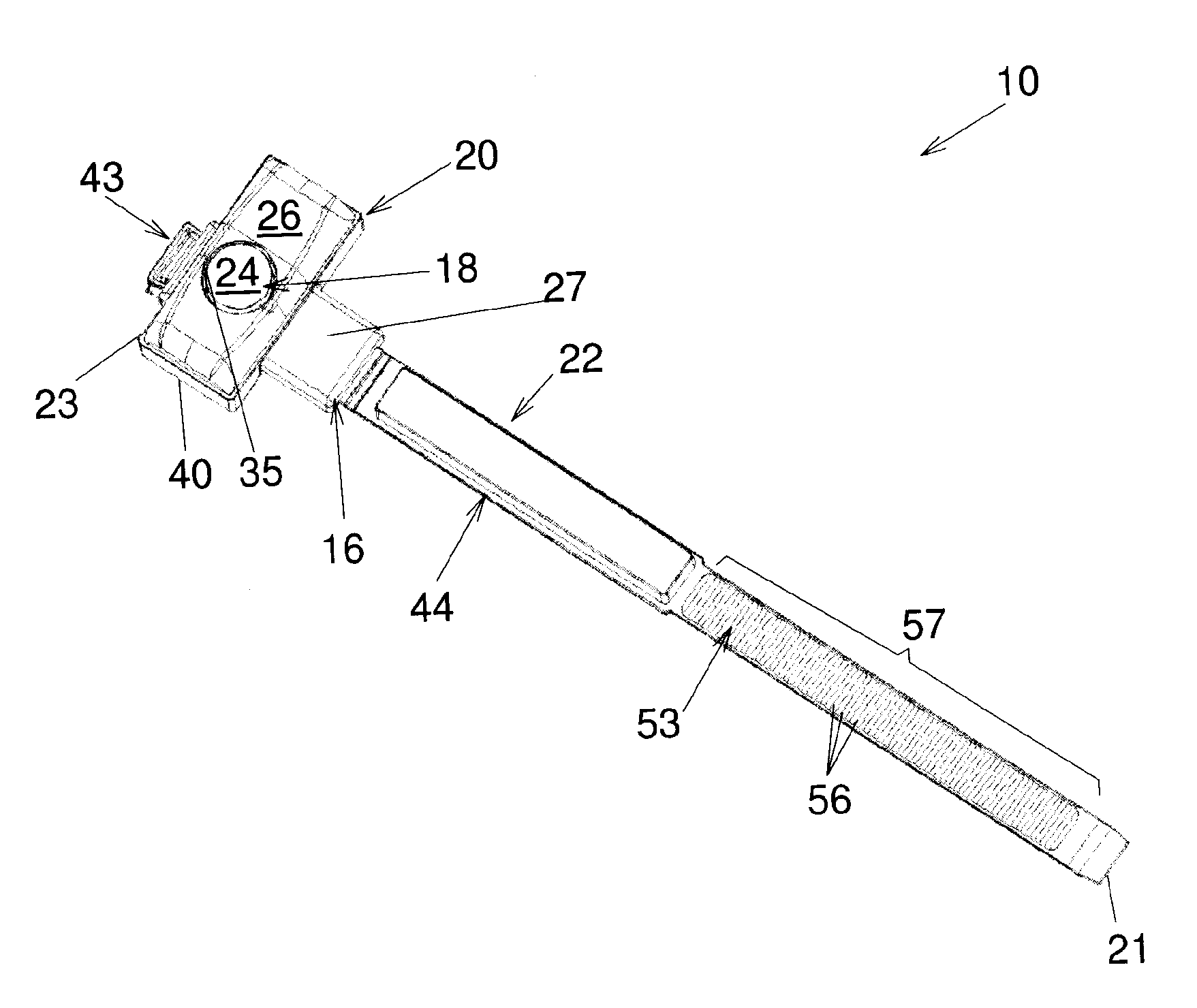
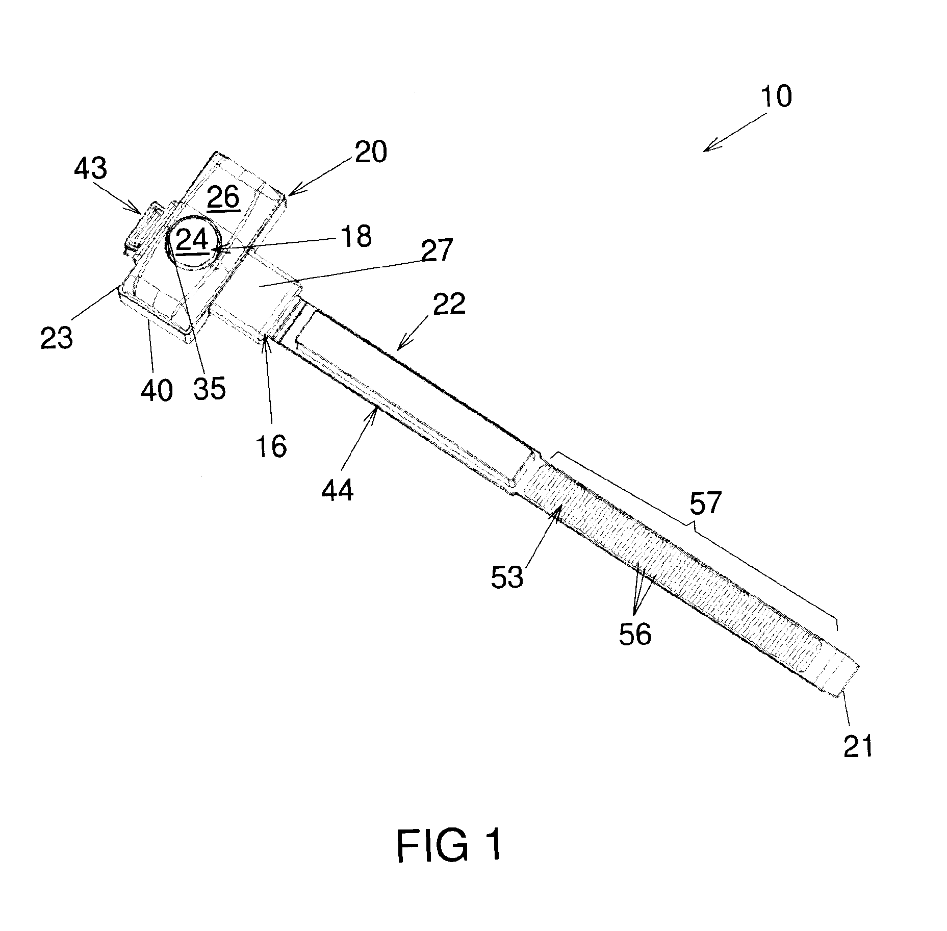
[0049]Referring to FIG. 1, there is shown a styptic device 10 in accordance with an embodiment of the present invention. As illustrated schematically in FIG. 11, the styptic device 10 is usable for substantially hemostatically sealing a percutaneous puncture 12 in a blood vessel 14 of a patient 11, only part of which is seen in FIG. 9. Returning to FIG. 1, the styptic device 10 includes a base 16 and a main compression element 18 extending from the base 16. An auxiliary compression element 20 is removably attachable the base 16. In some embodiments of the invention, the styptic device 10 includes a bracelet 22 mechanically coupled to the main compression element 18 for attaching the styptic device 10 to the patient 11. The bracelet 22 is configurable between an attached configuration in which the styptic device 10 is attached to the patient 11 and a detached configuration, in which the styptic device 10 is removable from the patient 11.

[0050]The bracelet defines a bracelet first end...


PUM


Abstract

A lockable flexible element including an attachment and a substantially elongated and flexible body defining a body first end and a substantially opposed body second end, the body defining a body serrated surface substantially longitudinally spaced apart from the body second end. The attachment includes a collar provided substantially adjacent the body second end; a tongue provided at least partially inside the collar and extending substantially longitudinally thereinto, the tongue defining a tongue serrated surface, the tongue being deformable between a tongue extended configuration and a tongue retracted configuration; and a safety catch removably insertable between the tongue and the collar with the tongue between the body serrated surface and the safety catch.

Description

FIELD OF THE INVENTION[0001]The present invention relates to the general field of attachments, usable for example for attaching two ends of an elongated flexible element to each other, and is particularly concerned with a lockable attachment. The present invention also relates to medical devices and is particularly concerned with a styptic device for hemostatically sealing percutaneous vascular punctures that incorporates such an attachment.BACKGROUND[0002]There exists a plurality of medical and / or surgical procedures that are carried out intravascularly or intralumenally. For example, in the treatment of vascular diseases, such as atherosclerosis, percutaneous angioplasty and stenting are now widely accepted procedures.[0003]Such procedures usually involve the percutaneous puncture and insertion of a hollow needle through a patient's skin and muscle tissue into the vascular system. A guide wire is then typically passed through the needle lumen into the patient's blood vessel access...

Claims


Application Information

Patent Timeline
IPC IPC(8): A61B17/00A44B19/24
CPCA61B17/0057A44B19/24A61B17/12A61B17/1325A61B17/1327A61B2017/12004B65D63/1072B65D2563/107Y10T24/45246
Inventor BELANGER, GUYGENDRON, BENMERCIER, NORMAND
Owner BENRIKAL SERVICES
Why Eureka
Try Eureka