High dynamic range image sensing device and image sensing method and manufacturing method thereof

Inactive Publication Date: 2013-05-23
HIMAX IMAGING LIMITED
View PDF2 Cites 6 Cited by
  • Summary
  • Abstract
  • Description
  • Claims
  • Application Information

AI Technical Summary

Benefits of technology

The present invention is about a device and method for capturing high dynamic range (HDR) images using a combination of image sensors with different integration times. The device includes a first pair of image sensors with one sensor having a long integration time and another sensor having a short integration time. The method involves sensing the image with the long integration time sensor and then sensing it again with the short integration time sensor. This allows for more details to be captured in the image, resulting in a higher dynamic range. The manufacturing method involves forming multiple pairs of image sensors on a wafer, each pair having a long and short integration time sensor. Overall, this technology allows for improved image quality and more flexibility in capturing high dynamic range images.

Problems solved by technology

However, there is a tradeoff between the image capturing speed and the resolution; that is, a rapid image capturing speed usually leads to low and poor resolution, while a slow image capturing speed is usually needed for high and good resolution.
In addition, in a high dynamic range environment, for example, capturing road condition images in a moving vehicle, the ordinary image sensor usually has poor color discrimination capabilities, especially in a dark environment.

Method used


Image

  • High dynamic range image sensing device and image sensing method and manufacturing method thereof
  • High dynamic range image sensing device and image sensing method and manufacturing method thereof
  • High dynamic range image sensing device and image sensing method and manufacturing method thereof

Examples


first embodiment

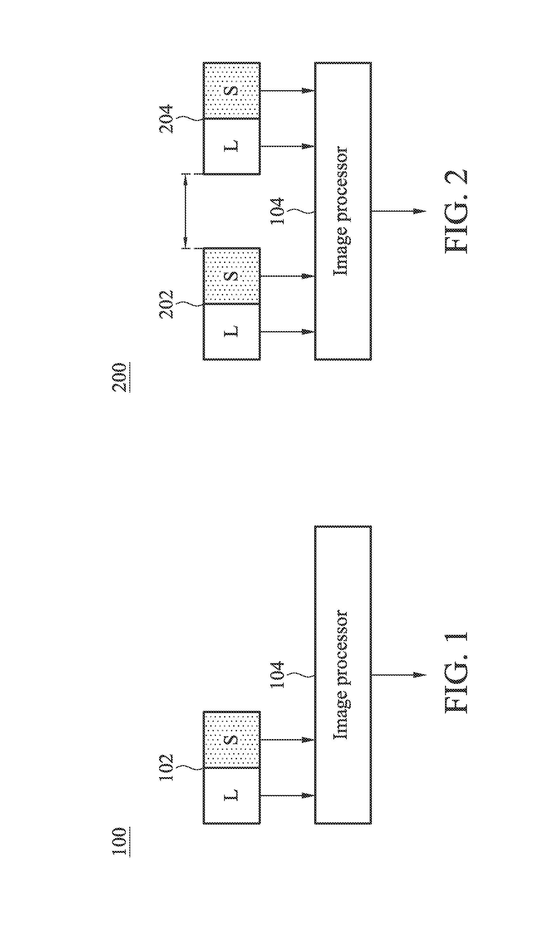
[0025]FIG. 1 shows a high dynamic range (HDR) image sensing device according to the present invention. The high dynamic range image sensing device 100 is used to sense an image in a high dynamic range. For example, the high dynamic range image sensing device 100 is for example a car surveillance recorder, a video event data recorder or a video parking image sensor, that records video or images.

[0026]The high dynamic range image sensing device 100 at least comprises a first pair of image sensors 102. The first pair of image sensors 102 has a first long integration time sensor L and a first short integration time sensor S. The first long integration time sensor L and the first short integration time sensor S are coupled and closely adjacent to each other. The first long integration time sensor is used for sensing the image with a long integration time, thus having better image sensitivity of the dark area, and the first short integration time sensor S is used for sensing the image wit...

second embodiment

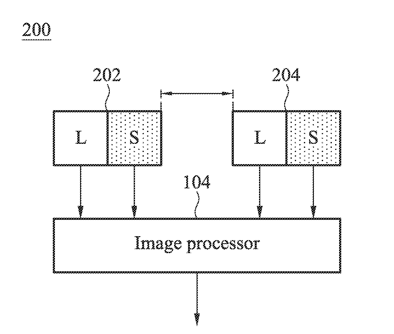
[0029]FIG. 2 shows a high dynamic range image sensing device 200 of the present invention for 3D image capturing. In this embodiment, the high dynamic range image sensing device 200 has two first pairs of image sensors, and each pair has a long integration time sensor L and a short integration time sensor S. As shown in FIG. 2, one of the first pairs of image sensors 202 is on the left side (for example, disposed on a left stereo camera), while the other of the first pair of image sensors 204 is on the right side (for example, disposed on a left stereo camera). The left and the right pair of image sensors 202 and 204 are separated by a distance, which mimic human eyes in order to create stereo vision.

third embodiment

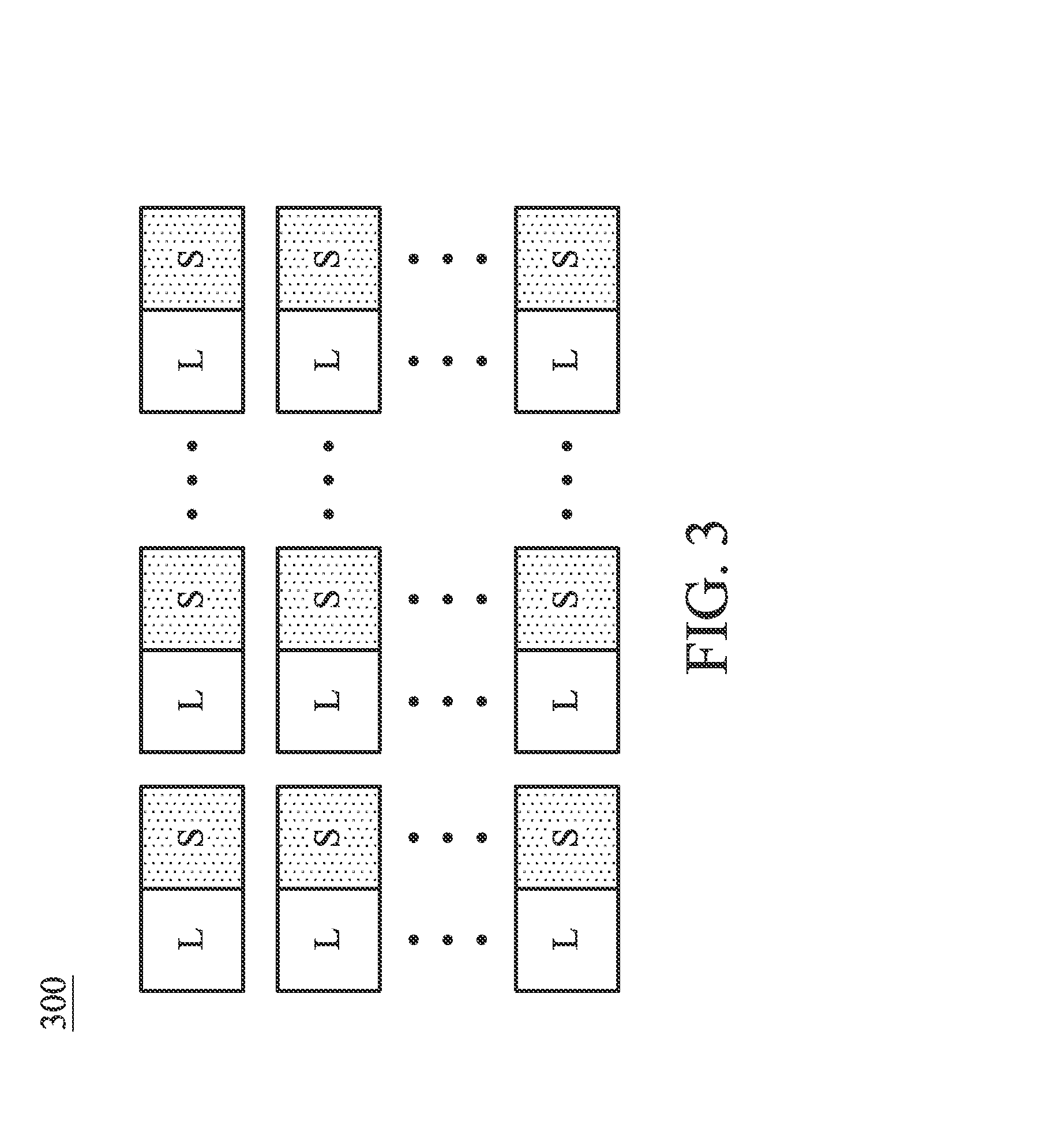
[0030]FIG. 3 shows a high dynamic range image sensing device 300 of the present invention for multi-dimension image capturing. In this embodiment, the high dynamic range image sensing device 300 has three or more pairs of image sensors, and each pair has a long integration time sensor L and a short integration time sensor S. In this embodiment, each of the image sensors receives images with different angles, thus creating the vision of compound eyes. The image sensor array shown in FIG. 3 is only for illustration purposes and should not be used to limit the present invention. Those skilled in the art can implement various image arrays for creating various types of compound eye visions, for example, apposition eye, superposition eye, or parabolic superposition eye visions, which conform with the advantages of the present embodiment of the invention, such as improving on high sensitivity (high resolution) and high frame rate, by using the long and short integration time sensors at the...


PUM

PropertyMeasurementUnit
Timeaaaaaaaaaa
Transparencyaaaaaaaaaa
Dynamicaaaaaaaaaa

Abstract

A high dynamic range (HDR) image sensing method is provided. The image sensor includes steps of: sensing an image with a long integration time by a first long integration time sensor; and sensing the image with a short integration time by a first short integration time sensor.

Description

BACKGROUND OF THE INVENTION[0001]1. Field of the Invention[0002]The present invention relates to an image sensing device, and in particular relates to a high dynamic range image sensing device which has long and short integration time sensors.[0003]2. Description of the Related Art[0004]For a conventional image sensor, a particular image capturing speed (i.e., exposure time or camera shutter speed) has to be determined and adjusted manually or automatically according to the illumination of the environment in order to quickly capture an image, for high resolution. However, there is a tradeoff between the image capturing speed and the resolution; that is, a rapid image capturing speed usually leads to low and poor resolution, while a slow image capturing speed is usually needed for high and good resolution. For video application, the image capturing speed also determines the frame rate.[0005]In addition, in a high dynamic range environment, for example, capturing road condition images...

Claims


Application Information

Patent Timeline
IPC IPC(8): H04N5/225H05K13/00H04N13/239
CPCH04N5/2355H04N9/045Y10T29/49002H04N13/0257H04N13/0239H04N13/257H04N13/239H04N23/741H04N25/134
Inventor LIU, CHIH-MIN
Owner HIMAX IMAGING LIMITED
Why Eureka
Try Eureka