
Fluid storage management system and method for monitoring fluid capacities and for controlling the transfer of fluid capacities within a fluid network

Active Publication Date: 2013-05-23
SIEMENS ENERGY GLOBAL GMBH & CO KG
View PDF10 Cites 5 Cited by
  • Summary
  • Abstract
  • Description
  • Claims
  • Application Information

AI Technical Summary

Benefits of technology

The fluid-reservoir management system described in this patent allows for improved monitoring and control of fluid capacities within a fluid network. Users can view the capacities and parameters of all fluid reservoirs in real-time, making it easy to make decisions about assigning orders. The system can also be accessed through a web interface or mobile-radio-network provider's mobile-radio network, making it easy for users to access and use the system. Additionally, a superordinate coordinating center can be used to coordinate the transfer of fluid capacities between different fluid-reservoir management systems. Overall, the system provides a more efficient and effective way to manage fluid reservoirs within a fluid network.

Problems solved by technology

That means there will nearly always be a negative margin of delay between dispatching the order and processing it because processing the order, for example the ordering of a certain amount of gas, is performed manually.
A problem frequently experienced by utility companies is that the available amounts of gas cannot be stored or withdrawn in a timely manner.
The activity of gas trading is greatly restricted by conventional communication media such as, for instance, telephone, fax, or e-mail and is often inefficient.

Method used


Image

  • Fluid storage management system and method for monitoring fluid capacities and for controlling the transfer of fluid capacities within a fluid network
  • Fluid storage management system and method for monitoring fluid capacities and for controlling the transfer of fluid capacities within a fluid network
  • Fluid storage management system and method for monitoring fluid capacities and for controlling the transfer of fluid capacities within a fluid network

Examples


Embodiment Construction

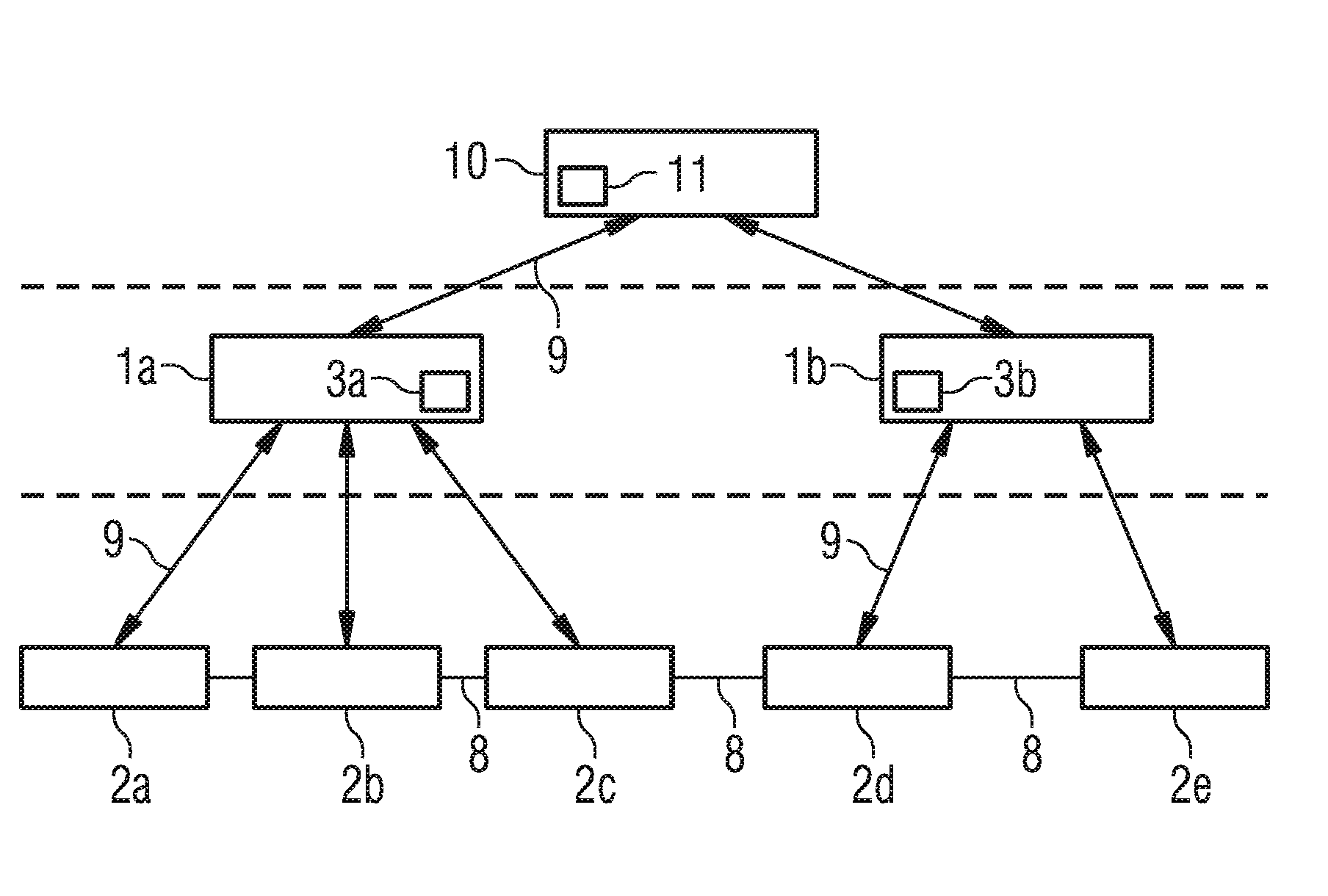
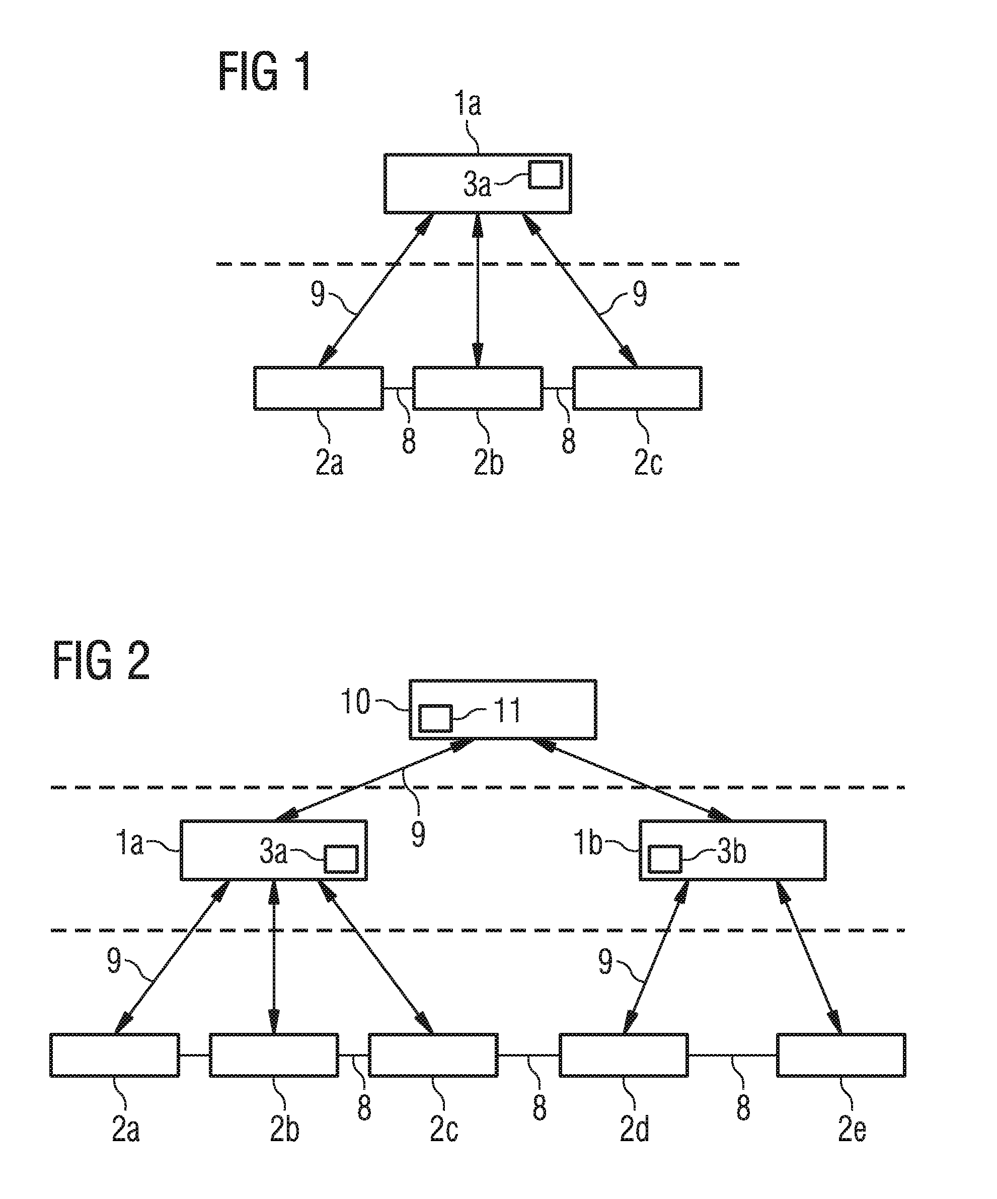
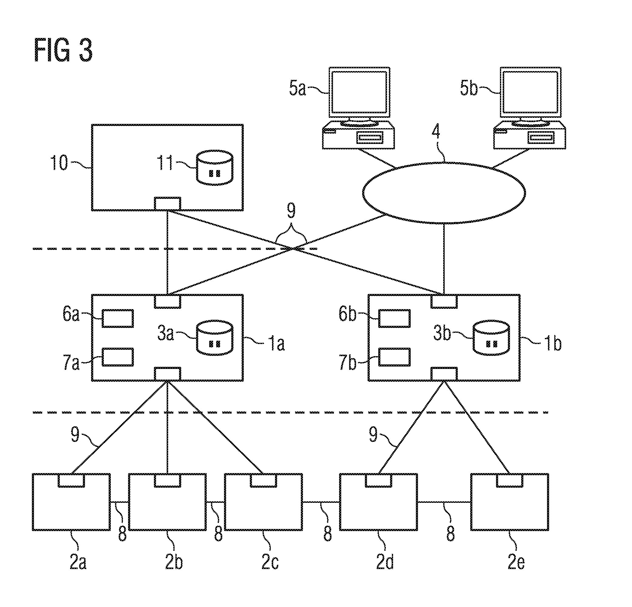
[0044]FIG. 1 is a schematic of a fluid-reservoir management system 1a having three fluid reservoirs 2a-2c embodied particularly as gas reservoirs. Fluid reservoirs 2a-2c are linked to each other via pipelines in a fluid network 8 so that fluid capacities can be transferred between fluid reservoirs 2a-2c through the pipelines. Each fluid reservoir 2a-2c is connected in a communication network 9 to fluid-reservoir management system 1a, in particular to a central computer unit 3a of fluid-reservoir management system 1a. All data, which is to say parameters of each fluid reservoir 2a-2c, in particular data about fluid capacity, pressures, prices of the fluid capacities, etc., is transmitted over said communication network 9. All information converges within fluid-reservoir management system 1a.

[0045]FIG. 2 shows a fluid-reservoir management system similar to that shown in FIG. 1. However, in this case two fluid-reservoir management systems 1a, 1b are coupled to a superordinate coordina...


PUM


Abstract

A fluid-reservoir management system for monitoring fluid capacities and controlling the transfer of fluid capacities within a fluid network includes a plurality of linked fluid reservoirs for storing the fluid capacities, a central computer unit in a communication network, the fluid reservoirs being linked to the communication network for transmitting data to and from the central computer unit, a communication portal provided in the communication network, a user interface for accessing the communication portal, a comparison unit for comparing fluid capacities and for comparing parameters of the fluid reservoirs and of the fluid network, and a control device for executing orders to transfer fluid capacities between at least two fluid reservoirs. The central computer unit coordinates the orders to transfer fluid capacities between at least two fluid reservoirs as a function of results of comparisons performed by the comparison unit and forwards the orders to the control device for executing.

Description

CROSS REFERENCE TO RELATED APPLICATIONS[0001]This application is the US National Stage of International Application No. PCT / EP2011 / 062640, filed Jul. 22, 2011 and claims the benefit thereof. The International Application claims the benefits of German application No. 10 2010 033 754.4 DE filed Aug. 9, 2010. All of the applications are incorporated by reference herein in their entirety.FIELD OF INVENTION[0002]The invention relates to a fluid-reservoir management system for transferring fluid capacities and controlling the transfer of fluid capacities within a fluid network. The invention relates further to a method for monitoring fluid capacities and controlling the transfer of fluid capacities within a fluid network.BACKGROUND OF INVENTION[0003]Through regulating of the gas market, the requirements to be met in terms of managing gas reservoirs for providing gas for seasonal operations are tending increasingly toward “gas on demand”. That means it should be possible for the gas to be ...

Claims


Application Information

Patent Timeline
IPC IPC(8): F17D3/00
CPCF17D3/00F17D1/04Y10T137/7287
Inventor BREMER, MARCOKLETSCHER, MARTIN
Owner SIEMENS ENERGY GLOBAL GMBH & CO KG
Learn More