Ventilation apparatus and cooking system having the same

Active Publication Date: 2013-05-23
SAMSUNG ELECTRONICS CO LTD +1
View PDF44 Cites 25 Cited by
  • Summary
  • Abstract
  • Description
  • Claims
  • Application Information

AI Technical Summary

Benefits of technology

The invention is a ventilation system that improves the ability to suck in polluted air or smoke. It has a purification system that removes oil from the air. The air is then quickly discharged to the indoor space, simplifying the duct system and increasing efficiency. The system uses a swirl to enhance suction efficiency.

Problems solved by technology

In a case when the downdraft hood is mounted, due to the space of a duct to discharge the air or smoke taken in occupies thereon, a space utilization rate is low, an installation of the duct is additionally needed, and additional costs for construction are incurred.
Furthermore, the downdraft hood is generally disposed in parallel to an ascending direction of air or smoke, which provides lower suction efficiency.
However, the noise of the t suction fan may be generated.
In addition, the size of a cooking system increases as the size of the suction fan increases.

Method used


Image

  • Ventilation apparatus and cooking system having the same
  • Ventilation apparatus and cooking system having the same
  • Ventilation apparatus and cooking system having the same

Examples


second embodiment

[0103]FIG. 9 is a drawing illustrating an inside structure of a body of a cooking system in accordance with the present disclosure. FIG. 10 is a drawing illustrating a cooking part of the cooking system of FIG. 9.

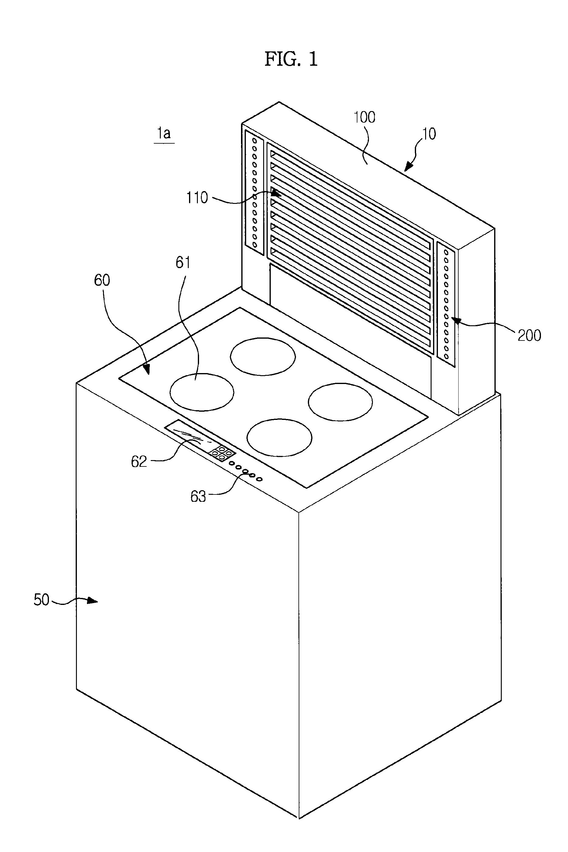
[0104]As illustrated on FIGS. 9 and 10, a cooking system 1b includes the body 50 forming the exterior of the cooking system 1b, the cooking unit 60 formed at an upper surface of the body 50, and the ventilation apparatus 10 mounted at an edge of an upper surface of the body 50.

[0105]The cooking unit 60 includes the heating apparatus 61 to apply heat on foods, the manipulation unit 63 to control the heating apparatus 61, and the display unit 62 to display the state and operation of the heating apparatus 61.

[0106]The ventilation apparatus 10 includes the housing 100 forming an exterior of the ventilation apparatus 10, a plurality of passages formed by a plurality of ducts, the suction guide 110 disposed at a front of the housing 100, the swirl generating unit 200 to discharge...

third embodiment

[0133]FIG. 15 is a drawing illustrating an inside structure of a body of a cooking system in accordance with the present disclosure.

[0134]As illustrated on FIG. 15, a passage of the cooking system in accordance with the third embodiment of the present disclosure is different in the structure from that of the cooking system in accordance with the second embodiment of the present disclosure.

[0135]The passage and the flow of the air passing through the passage will be mainly described on the drawings hereinafter.

[0136]FIG. 16 is a cross-sectional view illustrating the flow of air taken in by the cooking system of FIG. 15.

[0137]As illustrated on FIG. 16, the polluted air containing polluted substance is taken in to the suction port 120 through the suction hole 112 of the suction guide 110 by the suction force of the suction fan 300.

[0138]The polluted air taken in to the suction port 120 is introduced to the suction passage 130 connected to a lower side of the suction port 120.

[0139]A fi...

fourth embodiment

[0152]FIG. 18 is a drawing illustrating a structure of a cooking system in accordance with the present disclosure.

[0153]As illustrated on FIG. 18, a cooking system 1d includes the body 50 forming an exterior of the cooking system 1d, the cooking unit 60 formed at an upper surface of the body 50, and the ventilation apparatus 10 mounted at an edge of the upper surface of the body 50.

[0154]The cooking unit 60 includes the heating apparatus 61 to apply heat directly on foods, the manipulation unit 63 to control the heating apparatus 61, and the display unit 62 to display the state and operation of the heating apparatus 61.

[0155]The ventilation apparatus 10 includes the housing 100 forming an exterior of the ventilation apparatus 10 and configured to accommodate each component of the ventilation apparatus 10, the suction guide 100 disposed at a front of the housing 100, and a swirler fan 70 to discharge a portion of the air that is taken in so that a swirl is generated.

[0156]The ventila...


PUM

PropertyMeasurementUnit
Forceaaaaaaaaaa
Volatilityaaaaaaaaaa

Abstract

A ventilation system that allows air to be directly discharged indoors, a the ventilation system including a body and a ventilation apparatus provided at an edge of an upper surface of the body and configured to take in polluted air generated during cooking, wherein the ventilation apparatus includes a suction port configured to take in the polluted air, a suction fan provided at an inside the body and configured to generate a suction force for the polluted air to be taken in through the suction port, a passage through which the air taken in through the suction port passes, at least one filter mounted at an inside the passage and configured to purify the air passing through the passage, and an exit port communicating with one end portion of the passage and configured to discharge the air purified by the at least one filter indoors.

Description

CROSS-REFERENCE TO RELATED APPLICATIONS[0001]This application claims the priority benefit of Korean Patent Application No. 10-2011-0120288, filed on Nov. 17, 2011 in the Korean Intellectual Property Office, the disclosure of which is incorporated herein by reference.BACKGROUND[0002]1. Field[0003]Embodiments relate to a ventilation apparatus capable of easily discharging polluted air and smoke generated during cooking, and a cooking system having the same.[0004]2. Description of the Related Art[0005]In general, a hood configured to take in and discharge polluted air generated at the time of cooking is installed at an upper portion of a gas range.[0006]However, a kitchen island (an island kitchen) separated from a wall is recently in demand.[0007]In a case when a gas range or an electric range is mounted on the kitchen island, the hood, that is, a ventilation apparatus, is not mounted on a ceiling for an aspect of space utilization efficiency and design. Instead, a downdraft is instal...

Claims


Application Information

Patent Timeline
IPC IPC(8): F24C15/20
CPCF24C15/2035F24C15/2078F24C15/2042F24C15/2028F24C15/20F24F7/06
Inventor JEONG, HYUN KULEE, KYU SUKSHIN, KYU HOLEE, JIN HOJUNG, MOON IILEE, JUNG HEEHUR, NAHM KEON
Owner SAMSUNG ELECTRONICS CO LTD
Why Eureka
Try Eureka