Optical Self-Diagnosis of a Stereoscopic Camera System

Active Publication Date: 2013-05-16
HELLA KGAA HUECK & CO
View PDF9 Cites 46 Cited by
  • Summary
  • Abstract
  • Description
  • Claims
  • Application Information

AI Technical Summary

Benefits of technology

The present invention is about a method to diagnose the health of a camera system using depth images. The method can detect issues like soiling, dirt accumulation, and poor lighting conditions. By calculating the depth image and comparing it with a threshold value, the method can issue a warning if the depth values fall beneath the threshold. This helps to avoid complex image analysis and can be adjusted for different ambient environments. Overall, the method simplifies the process of diagnosing camera system health and ensures reliable image quality.

Problems solved by technology

When the camera system is a component of a monitoring system which automatically evaluates recorded images (e.g. a person counting system), there is a likelihood that detection errors consequently occur and remain unnoticed.
Most methods for optical self-diagnosis of a camera system which were developed up until now are based on gray-scale pictures supplied directly by the camera and require high computing power for evaluation and an enormous amount of memory.
As has already been mentioned above, such a solution comes with the disadvantage that high computing power and high memory capacity needs to be provided in order to evaluate the images.

Method used


Image

  • Optical Self-Diagnosis of a Stereoscopic Camera System
  • Optical Self-Diagnosis of a Stereoscopic Camera System
  • Optical Self-Diagnosis of a Stereoscopic Camera System

Examples


Embodiment Construction

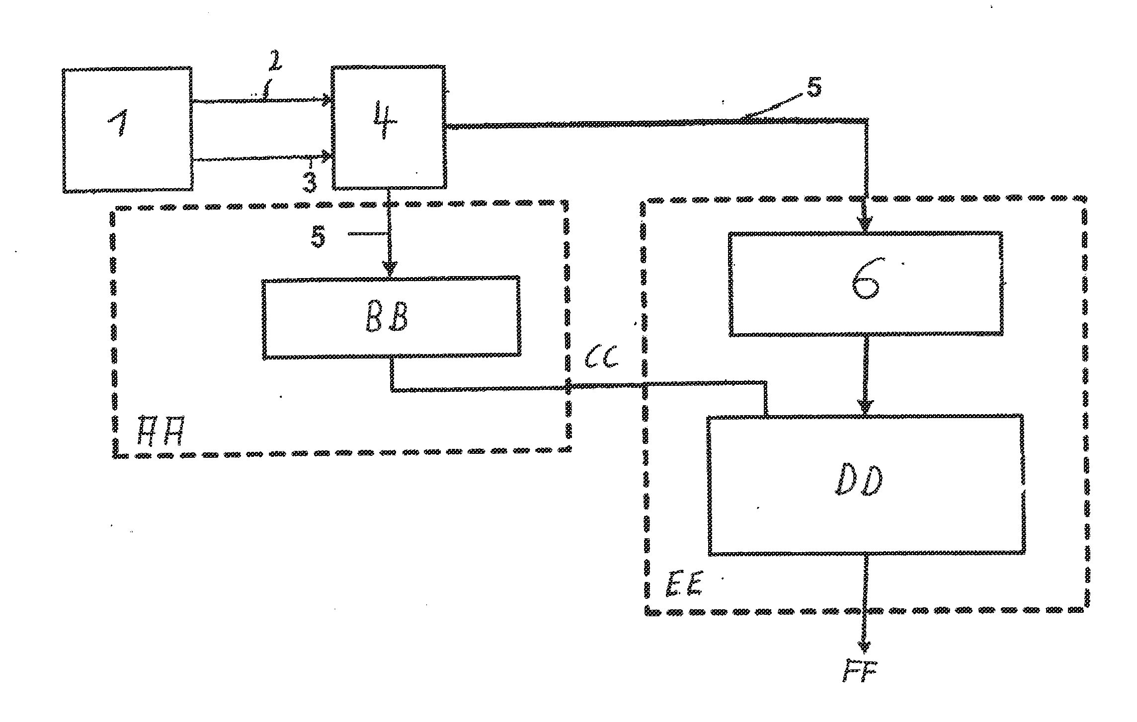
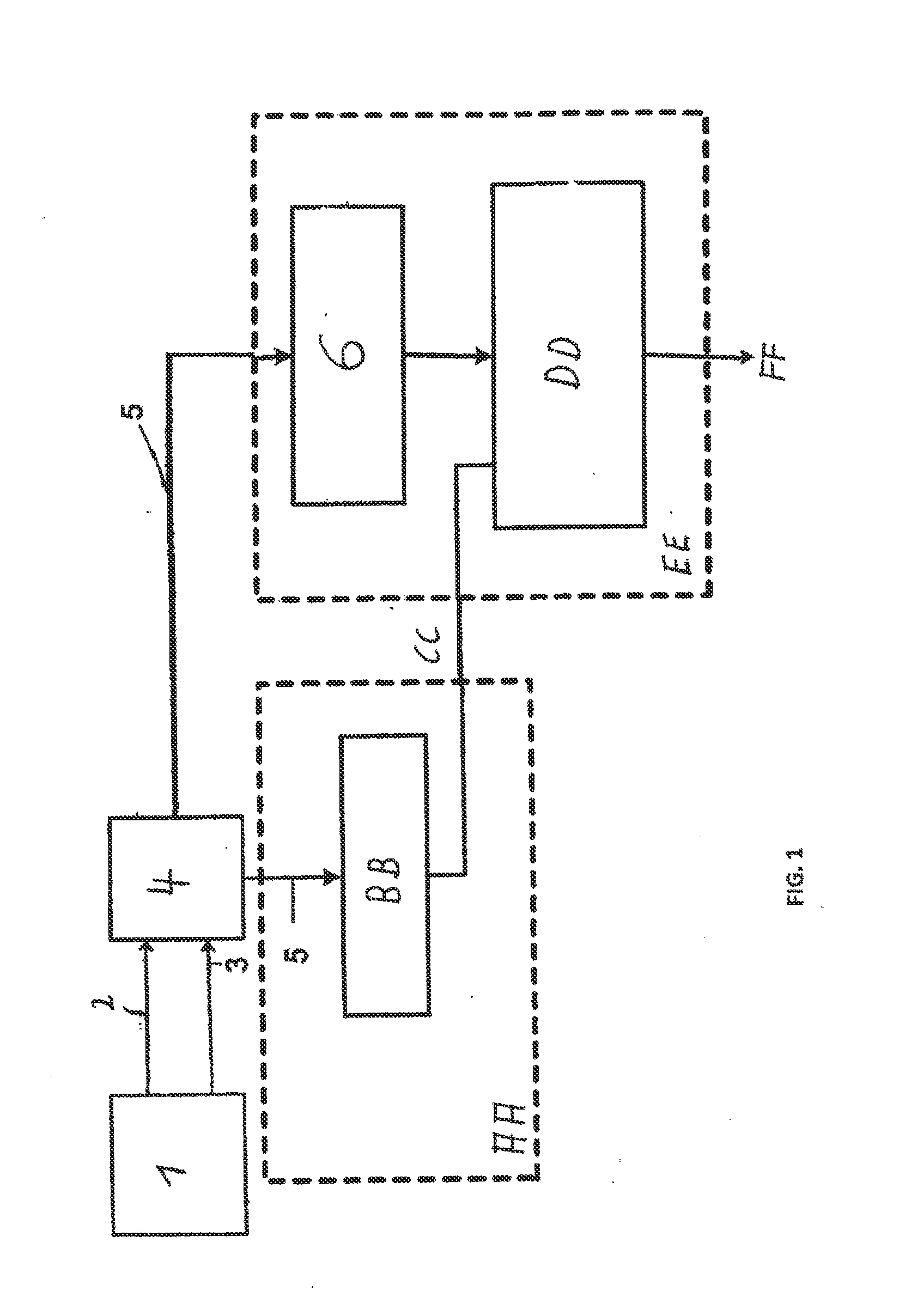
[0024]FIG. 1 shows a schematic functional sequence of a method with which a camera system can be tested automatically for functionality. This camera system concerns a numbering system. At the first step, a stereo camera 1 of the camera system simultaneously records a right partial image 2 and a left partial image 3 of an object from different perspectives. The two partial images 2, 3 are rectified at first by an algorithm, i.e. they are rectified and transformed in such a way as if they had been recorded by an ideal stereo camera system aligned in parallel. The right partial image 2 and the left partial image 3 are compared to each other line by line in a matching method 4, and mutually corresponding pixels in the two partial images 2 and 3 may be determined. A disparity value is assigned to each of these pixels, which disparity value is defined as a horizontal parallax between the position of the mutually corresponding pixels in the two partial images 2 and 3. A depth image, which ...


PUM


Abstract

The present invention relates to a method for the optical self-diagnosis of a camera system and to a camera system for carrying out the method. The method comprises recording stereo images obtained from in each case at least two partial images (2, 3) creating a depth image, that is to say a disparity map (5) given by calculated disparity values, determining a number of valid disparity values (6) of the disparity map (5), and outputting a warning signal depending on the number of valid disparity values determined. A device for carrying out such a method comprises a stereo camera (1) having at least two lenses (7,8) and image sensors, an evaluation unit and a display unit.

Description

CROSS-REFERENCE TO RELATED APPLICATIONS[0001]This application is a continuation of pending International Application No. PCT / EP2011 / 003053 filed on Jun. 17, 2011, which designates the United States and claims priority of the pending German Application No. 10 2010 024 666.2 filed on Jun. 18, 2010. Each of the abovementioned patent application is incorporated by reference herein in its entirety.TECHNICAL FIELD[0002]The present invention relates to a method for optical self-diagnosis of a camera system, and to a camera system for carrying out such a method.BACKGROUND[0003]Camera systems—and stereo camera systems in particular—react sensitively to dirt accumulation of any kind. When the camera system is a component of a monitoring system which automatically evaluates recorded images (e.g. a person counting system), there is a likelihood that detection errors consequently occur and remain unnoticed. In order to prevent impairments in the image quality and detection errors caused thereby,...

Claims


Application Information

Patent Timeline
IPC IPC(8): H04N13/02
CPCH04N13/00H04N17/002G06T7/0002H04N13/0246G06T2207/30168H04N13/0296H04N13/0055G06T2207/10012H04N13/189H04N13/246H04N13/296
Inventor SONG, MIAOLOJEWSKI, BJORN
Owner HELLA KGAA HUECK & CO
Why Eureka
Try Eureka