
Straight tube LED lamp, lamp socket set, and lighting fixture

a technology of led lamps and sockets, applied in the direction of semiconductor devices for light sources, lighting and heating apparatus, coupling device connections, etc., can solve the problems of reduced light emission efficiency of led lamps, reduced life of led lamps, and likely shortened lighting circuit life. , to achieve the effect of low risk of electric shock

Active Publication Date: 2013-05-16
PANASONIC CORP +1
View PDF8 Cites 54 Cited by
  • Summary
  • Abstract
  • Description
  • Claims
  • Application Information

AI Technical Summary

Benefits of technology

The present invention aims to provide a straight tube LED lamp, a lamp socket set, and a lighting fixture that have a low risk of electric shock.

Problems solved by technology

In this type of alternating current-lit LED lamp, the lighting circuit is built into the LED lamp, and therefore a lifespan of the lighting circuit is likely to be shortened due to heat generated by the LEDs.
As a result, the lifespan of the LED lamp itself is also likely to be shortened.
Further, the temperature of the LEDs may be raised by heat generated in the lighting circuit, leading to a reduction in the light emission efficiency of the LEDs.
Moreover, when the lighting circuit is inbuilt, a size and a cost of the LED lamp increase.
Therefore, when a current leaks to the heat sink from an LED module or the lighting fixture, an electric shock may occur upon touching the heat sink.
In a direct current-lit LED lamp in particular, a voltage to ground of the heat sink is a simple sum of a power supply voltage and a lamp voltage, which is larger than an effective value of a voltage to ground of an alternating current-lit LED lamp, and therefore the risk of an electric shock is high.

Method used


Image

  • Straight tube LED lamp, lamp socket set, and lighting fixture
  • Straight tube LED lamp, lamp socket set, and lighting fixture
  • Straight tube LED lamp, lamp socket set, and lighting fixture

Examples


first embodiment

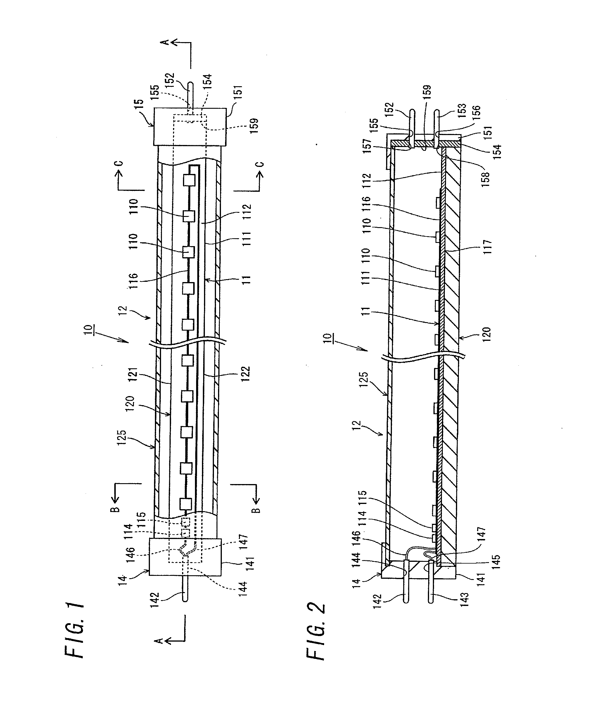
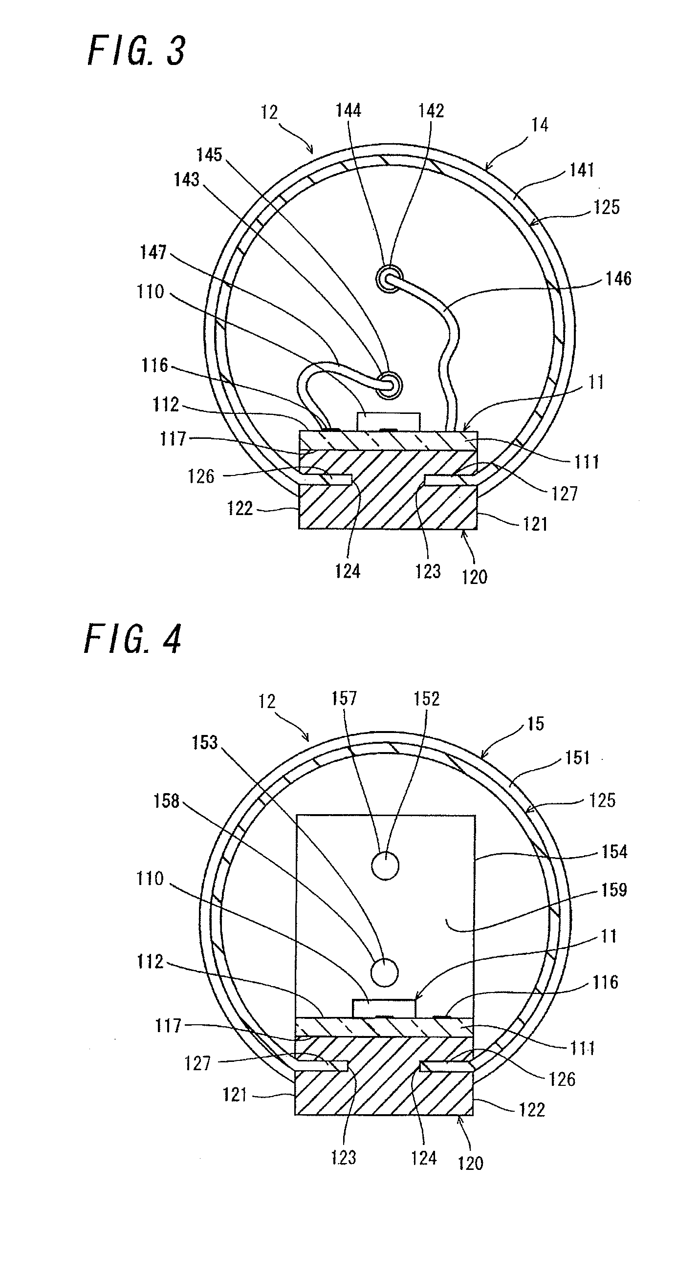
[0055]As shown in FIGS. 1 and 2, a straight tube LED lamp (to be referred to as a “lamp” hereafter) 10 according to this embodiment includes a straight tube 12 housing in its interior a plurality of light emitting diodes (to be referred to as “LEDs” hereafter) 110, a first cap 14 for forming a power feeding connection to the plurality of LEDs 110, and a second cap 15 for grounding. The first cap 14 is provided on one axial direction end side of the straight tube 12, while the second cap 15 is provided on another axial direction end side of the straight tube 12. The plurality of LEDs 110 are included in an LED module 11. The straight tube 12 is constituted by a heat sink 120 and a cover 125.

[0056]The LED module 11 includes an elongated rectilinear substrate 111. The plurality of LEDs 110 are mounted on a mounting surface 112 of the substrate 11, for example, in a single straight line along a lengthwise direction of the substrate 111 together with a single thermal fuse 114 and a singl...

second embodiment

[0084]When the straight tube LED lamp described above has identical dimensions and identical caps to a straight tube fluorescent lamp, the straight tube LED lamp may be mistakenly connected to a lighting fixture having a lighting circuit for a straight tube fluorescent lamp.

[0085]FIGS. 7A and 7B are external perspective views showing a straight tube LED lamp 10 for solving this problem. For the purpose of clarity, like kind elements are assigned the same reference numerals as depicted in the first embodiment.

[0086]The lamp 10 includes a single straight tube 22 that is formed from a translucent synthetic resin material, but not limited thereto. The single straight tube 22 may be a glass tube. A first cap 14 for power feeding is provided on one axial direction end side of the straight tube 22, and a second cap 15 for grounding is provided on another axial direction end side of the straight tube 22.

[0087]A substrate (see FIG. 1, for example) formed from a printed board having a slightl...

third embodiment

[0126]When the straight tube 22 is formed from a translucent synthetic resin material, the straight tube LED lamp may move in the lengthwise direction as a result of bending, thermal expansion, and thermal contraction of the straight tube LED lamp.

[0127]FIG. 19 shows a lighting fixture 19 for solving this problem. For the purpose of clarity, like kind elements are assigned the same reference numerals as depicted in first or second embodiment. The lighting fixture 19 is an embedded lighting fixture for one or a plurality of straight tube fluorescent lamps, and includes one or a plurality of straight tube LED lamps 10. The lighting fixture 19 is not limited to an embedded lighting fixture. The lighting fixture 19 may also be applied to a ceiling mounted lighting fixture.

[0128]The lighting fixture 19 includes an elongated casing 191 (see FIG. 9) that is embedded in a ceiling surface and has an open lower surface, first and second lamp sockets 37, 38 disposed on respective lengthwise di...


PUM


Abstract

A straight tube LED lamp includes: a straight tube in which a plurality of light emitting diodes is housed; a first cap for forming a power feeding connection to the plurality of light emitting diodes, provided on one axial direction end side of the straight tube; and a second cap for grounding, provided on another axial direction end side of the straight tube. A first terminal for forming an electrical connection to a power feeding terminal of a first lamp socket is provided in the first cap. A second terminal for forming an electrical connection to a grounding terminal of a second lamp socket is provided in the second cap.

Description

TECHNICAL FIELD[0001]The present invention relates to a straight tube LED (light emitting diode) lamp, a lamp socket set to which the straight tube LED lamp is connected, and a lighting fixture that uses the straight tube LED lamp and the lamp socket set.BACKGROUND ART[0002]An LED lamp, which has a longer lifespan and consumes less power than a fluorescent lamp, has been proposed as a replacement for a fluorescent lamp to achieve reductions in power consumption and a frequency with which the lamp is replaced at the end of its life (for example, Japanese Patent Application Publication Nos. 2008-103304, 2009-266432, and 2008-282793). For example, a straight tube LED lamp serving as a replacement for a straight tube fluorescent lamp includes an elongated substrate having a length that corresponds to a fluorescent lamp, and a plurality of LEDs arranged on the substrate in its lengthwise direction. An aluminum heat sink constituting a part of an outer shell is attached to an opposite sid...

Claims


Application Information

Patent Timeline
IPC IPC(8): H05B33/06H01J5/50H05B33/08H05B44/00
CPCH01R33/0854H01R13/7175F21Y2101/02H05B33/0803H01J5/50F21K9/175H01R33/02F21Y2103/003H05B33/06F21V14/02F21V29/50F21Y2103/10F21Y2115/10F21K9/272H05B45/00
Inventor FUKANO, SATOSHINISHIHAMA, NOBUMICHIYAMANAKA, TADASHIMASUKO, FUMIHIKOSAITO, TAKESHINAKAGAWA, HIROKIHIEDA, MASANAOITO, KENICHISUGISHITA, NAOKIONO, KEISUKESHIMIZU, KEIICHIKUMASHIRO, SHINICHIOSADA, TAKESHI
Owner PANASONIC CORP
Learn More