Rotatable electrical coupling device

Inactive Publication Date: 2013-05-09
ONDAL MEDICAL SYST
View PDF1 Cites 6 Cited by
  • Summary
  • Abstract
  • Description
  • Claims
  • Application Information

AI Technical Summary

Benefits of technology

[0015]In a preferred form of the invention, the coupling device includes at least one further (i.e. third) electrical contact member to provide an electrical connection between the first casing and the second casing. Thus, the third contact member operates to ensure that both of the first and second casings, which preferably serve as outer or shield conductors around inner or core conductors formed by the first and second electrical contact members respectively, remain grounded. In a highly preferred embodiment of the invention, the at least one biasing member is electrically conductive and thus forms the further (third) electrical contact member providing an electrical connection between the first casing and the second casing. Preferably, a plurality of biasing members (i.e. third contact members) is provided. Each biasing member (or third electrical contact member) may comprise, or be formed as, a spring element (e.g. a leaf-spring) and desirably presents a very small contact area for contacting the respective first or second casing. By providing a reduced contact area in this way, it is possible to minimise frictional interference during the relative rotation of the first and second connectors.
[0016]In a preferred form of the invention, the rotatable electrical coupling device further comprises a retaining member configured to secure or lock the second connector against removal from the coupled state with the first connector. For example, when the second connector is received within the first casing in

Problems solved by technology

It has been found, however, that such coupling designs are not always suitable to meet the requirements demanded of equipment mounting systems in modern healthcare, commercial and industrial applications

Method used


Image

  • Rotatable electrical coupling device
  • Rotatable electrical coupling device
  • Rotatable electrical coupling device

Examples


Example

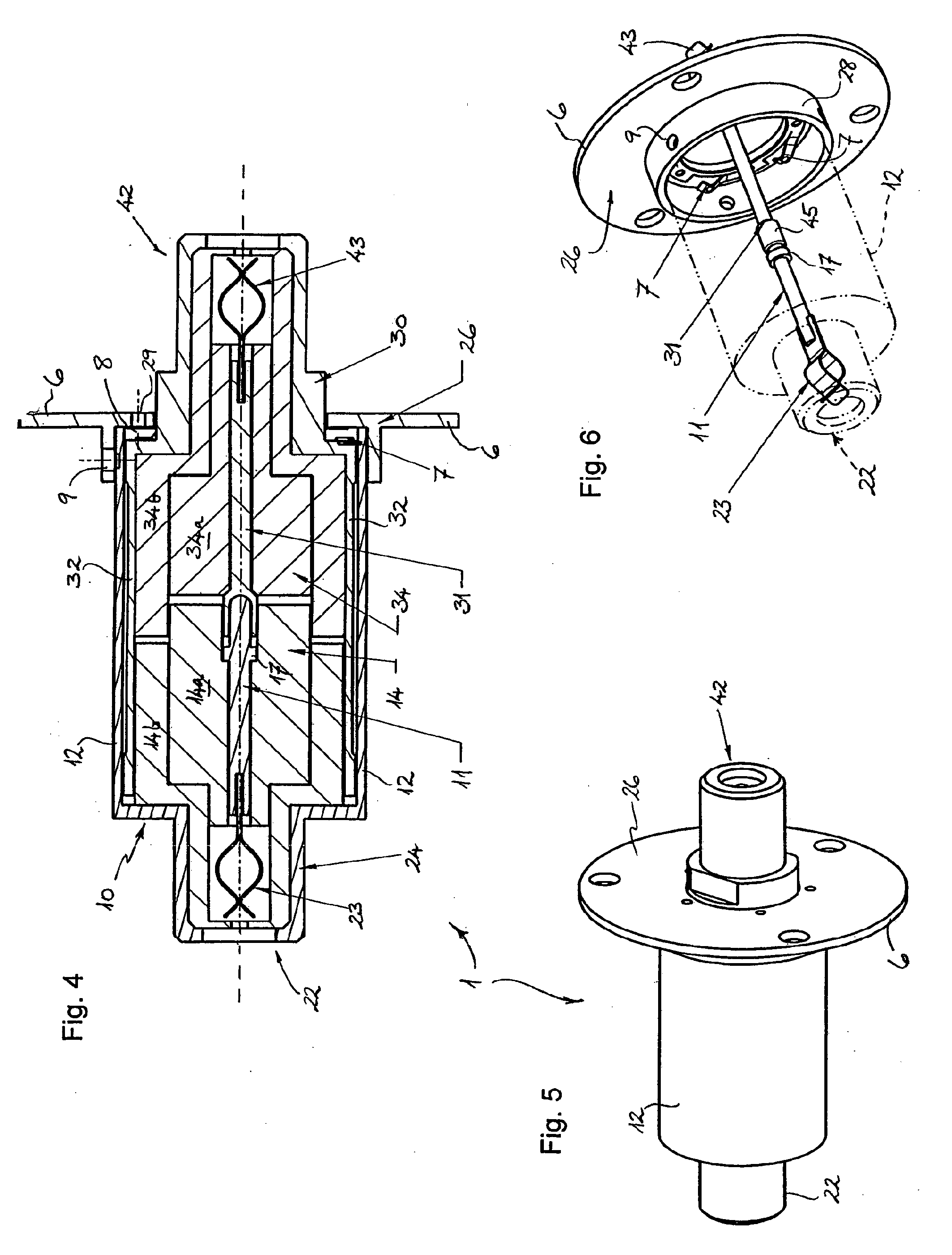
[0035]With reference firstly to FIGS. 1 to 3 of the drawings, a rotatable electrical coupling device 1 for a high-frequency and / or high-speed data transmission according to a preferred embodiment of the invention is illustrated. The electrical coupling device 1 has a first connector 10 and a second connector 30. which are shown in FIG. 1 and FIG. 3 of the drawings in a combined or coupled state in rotatable engagement with one another. The exploded view of the coupling device 1 in FIG. 2 more clearly illustrates the various components of each of the first and second connectors 10, 30.

[0036]With particular reference to FIGS. 1 and 2, therefore, the first connector 10 of the coupling device 1 can be seen to include a first electrical contact member 11 which is generally elongate and formed as a rod- or pin-like member. This rod- or pin-like first contact member 11 has a generally circular cross-section and extends centrally of the first connector 10. Furthermore, the first contact mem...


PUM


Abstract

A rotatable electrical coupling device incorporates a first connector having a first electrical contact member adapted to conduct or transmit a high-frequency and/or high-speed data signal, and a second connector having a second electrical contact member adapted to conduct or transmit a high-frequency and/or high-speed data signal. The second connector is configured to be coupled with the first connector for substantially free or unimpeded rotation about an axis (X) relative to the first connector, the first and second electrical contact members being configured to engage one another and to maintain uninterrupted electrical contact throughout a relative rotational movement between the first and second connectors in a coupled state.

Description

TECHNICAL FIELD[0001]The present invention relates to a rotatable electrical coupling device and, more particularly, to a coupling device configured to provide an uninterrupted electrical connection between coupled components throughout relative rotation thereof about a rotational axis of the device.[0002]The rotatable electrical coupling of the invention is desirably designed for use in a swivel or pivot joint of a mounting arm, such as the type of mounting arm used for supporting or suspending technical equipment, e.g. in medical or in commercial or industrial environments. In this way, the rotatable coupling of the invention is able to provide reliable electrical communication through the joint of the mounting arm to the technical equipment, regardless of rotary movement of that joint. As such, it will be convenient to hereinafter describe the invention in this particular context. It will be noted, however, that the rotatable electrical coupling device of the invention is not lim...

Claims


Application Information

Patent Timeline
IPC IPC(8): H01R24/40
CPCH01R39/64H01R35/04H01R13/6471H01R13/6592H01R24/40H01R2103/00H01R24/542
Inventor GOBEL, ANDREASICKLER, FRITZ
Owner ONDAL MEDICAL SYST
Why Eureka
Try Eureka