
Frame for solar panels

a solar panel and frame technology, applied in the direction of heat collector mounting/support, semiconductor/solid-state device details, lighting and heating apparatus, etc., can solve the problems of frame deflection and twisting, not always providing the desired structural strength and rigidity

Inactive Publication Date: 2013-05-09
TSMC SOLAR LIMITED
View PDF2 Cites 18 Cited by
  • Summary
  • Abstract
  • Description
  • Claims
  • Application Information

AI Technical Summary

Benefits of technology

The present patent is about a new solar cell frame design that is stronger and more lightweight than previous frames, which are made of anodized aluminum. The new frame design includes a reinforcing member that is inserted into an outer sleeve, providing better support and reducing bending stresses on the frame. The reinforcing member can be locked into position using a locking system. The new frame design helps to minimize damage to the solar panel and allows for proper mounting on a support structure. The technical effects of this new frame design include increased structural strength, reduced weight, and improved mounting capabilities for solar panels.

Problems solved by technology

Solar cell frames experience static and dynamic loads created by the wind, snow, dead weight of the solar panel, and thermal expansion all of which cause deflection and twisting of the frames.
Aluminum, however, may not always provide the desired structural strength and rigidity to properly support the solar panel and minimize bending stresses particularly in the top glass cover sheet.

Method used


Image

  • Frame for solar panels
  • Frame for solar panels
  • Frame for solar panels

Examples


example

Computer Stress Analysis

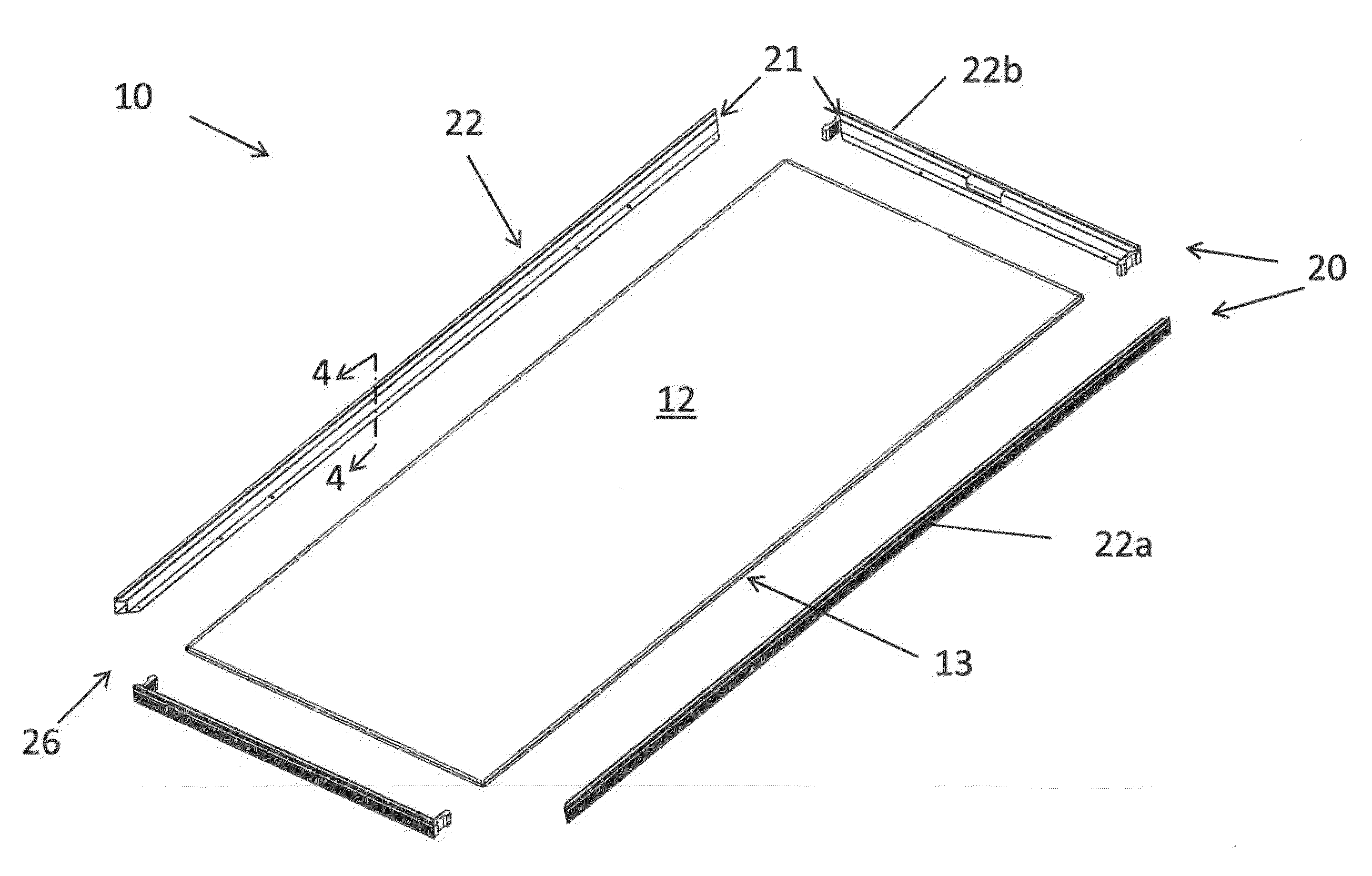
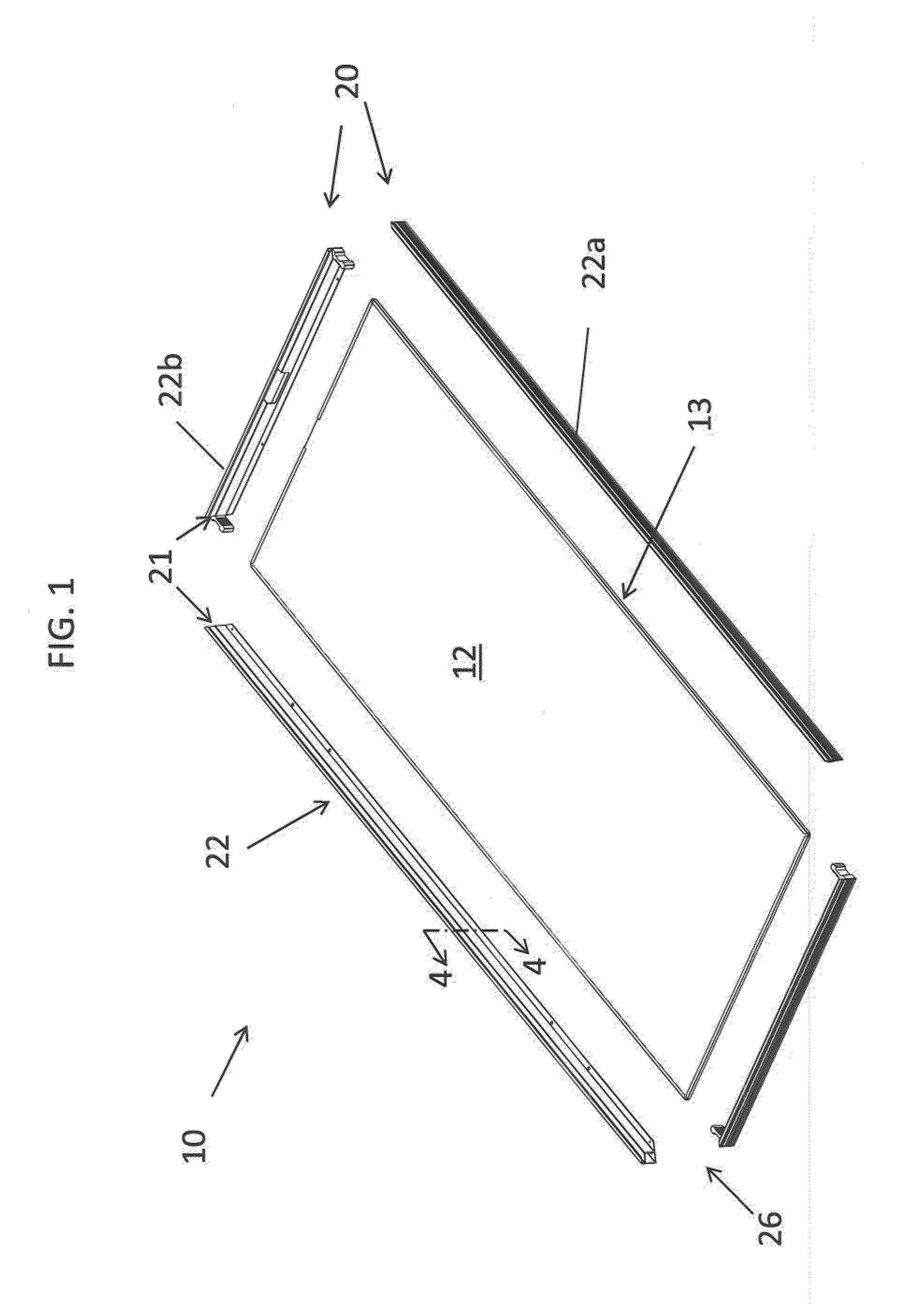
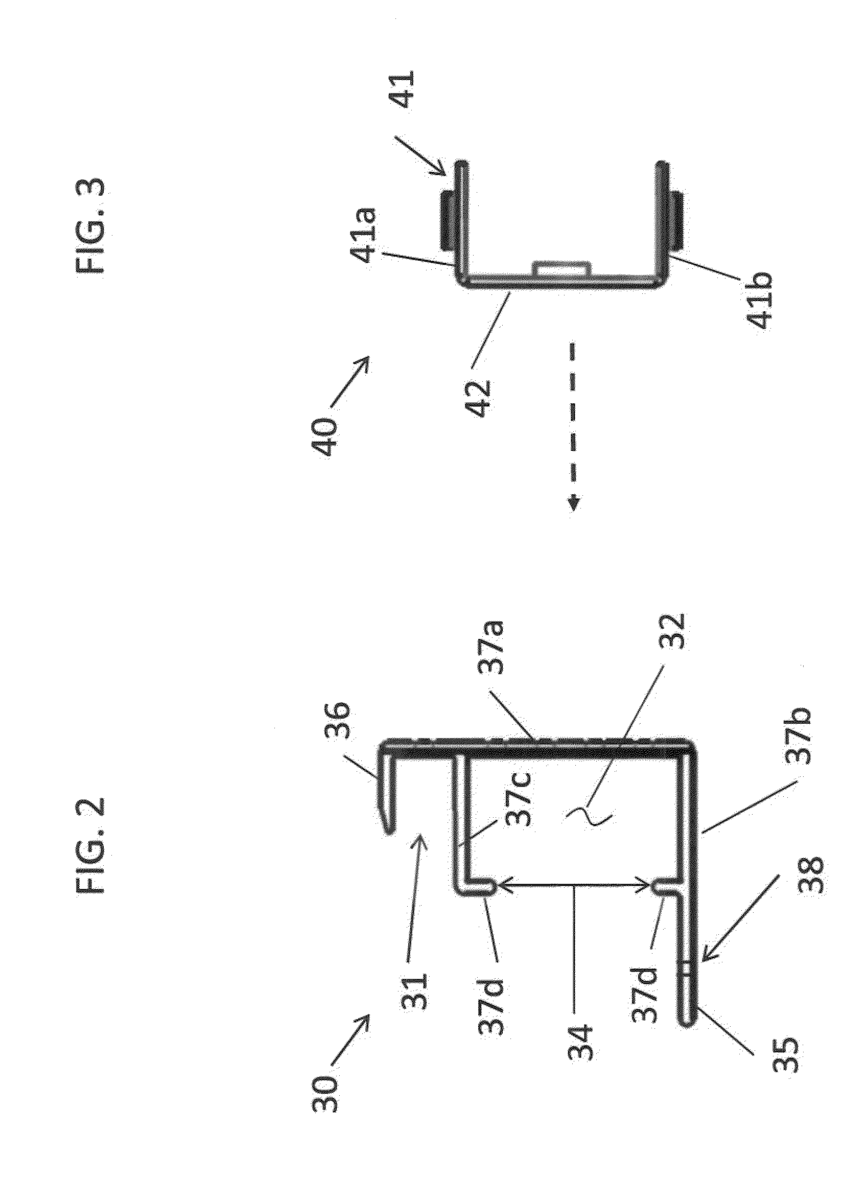
[0054]The inventors performed a computer-simulated static structural stress analysis to compare an unreinforced solar panel frame with a reinforced frame 20 utilizing reinforcing members 40 and outer sleeve 30 according to embodiments of the present disclosure. The simulation was performed using ANSYS version 12.1 structural stress analysis software available from ANSYS, Inc. The virtual solar modules analyzed were configured similar to solar module 10 shown in FIG. 1. The modules included a glass top cover sheet 5.8 mm thick and perimeter frame measuring 1656 mm long by 650 mm wide by 35 mm high. The unreinforced frame analyzed was made of grade / type 6063 T5 aluminum. The reinforced frame was made of the same aluminum outer sleeve but with a grade / type SUS 304 steel reinforcing member.

[0055]The maximum principal stress on the glass cover sheet at the physical center of the solar panel was determined by the stress analysis. This is the area of the greatest de...


PUM

PropertyMeasurementUnit
lengthaaaaaaaaaa
tensile strengthaaaaaaaaaa

Abstract

A frame member is disclosed for a mounting a solar panel in a solar module. Embodiments of the frame member include an elongated outer sleeve having a channel configured for receiving an elongated inner reinforcing member disposed therein. The reinforcing member may be slidably inserted into the channel in some embodiments and is operable to structurally strengthen the outer sleeve. The reinforcing member may be made of a material having a greater tensile strength than the outer sleeve. A method for assembling the frame is also provided.

Description

FIELD[0001]The present disclosure generally relates to photovoltaic solar cells, and more particularly to structural frames for supporting solar panels and methods for assembling the same.BACKGROUND[0002]Solar cells represent one class of devices which harness a renewable source of energy in the form of light that is converted into useful electrical energy which may be used for numerous applications. Thin film solar cells are one type of solar cell comprised of multi-layered semiconductor structures formed by depositing various thin layers and films of semiconductor and other materials on a substrate that are operable to capture and convert light energy into electricity. Multiple solar cells are positioned between transparent / translucent top cover and bottom backing sheets of material to form flat panels commonly rectangular in configuration. These solar panels are environmentally sealed and the generally transparent top cover sheet is conventionally glass, which may be tempered in ...

Claims


Application Information

Patent Timeline
Patent Type & Authority Applications(United States)
IPC IPC(8): H01L31/048B23P11/00H01L23/32H01L31/18
CPCF24J2/5211F24J2002/4656Y10T29/49826Y02E10/47Y10T29/49355H02S30/10F24S25/20F24S2080/09Y02E10/50
Inventor LI, SZU-HANFU, THOMAS TONG HONG
Owner TSMC SOLAR LIMITED
Learn More