Bone drill

a drill bit and bone technology, applied in the field of bone drills, can solve the problems of difficult to guide a drill bit inside a bone, more difficult, and the drill component to jam, so as to reduce the number of drill bits, reduce the strain on the subject, and accelerate the operation

Inactive Publication Date: 2013-05-02
UNIV OF OULU
View PDF16 Cites 17 Cited by
  • Summary
  • Abstract
  • Description
  • Claims
  • Application Information

AI Technical Summary

Benefits of technology

The invention is a device and method for drilling bones that reduces damage to healthy tissue and allows for more accurate localization of treatment. The device includes a superelastic metal-alloy bit that can bend in the drill channel, making it possible to direct drilling inside the bone. With the aid of this invention, bone drilling can be done safely and in a controlled manner. The invention can also be used to treat difficult conditions, such as necrosis in the bone marrow, by revitalizing bone tissue.

Problems solved by technology

Generally, it is difficult to guide a drill inside a bone.
It is even more difficult if a curve must be made in the channel or hole.
Further, in such a solution even small movements of the drill can cause the drill component to jam.
It is difficult to drill actual holes using this method, because when it returns to its original curved shape the arm of the drill and the suction component catches on the walls of the already drilled hole and the rotating arm will then begin to wear the wall of the hole.

Method used


Image

  • Bone drill
  • Bone drill
  • Bone drill

Examples


first embodiment

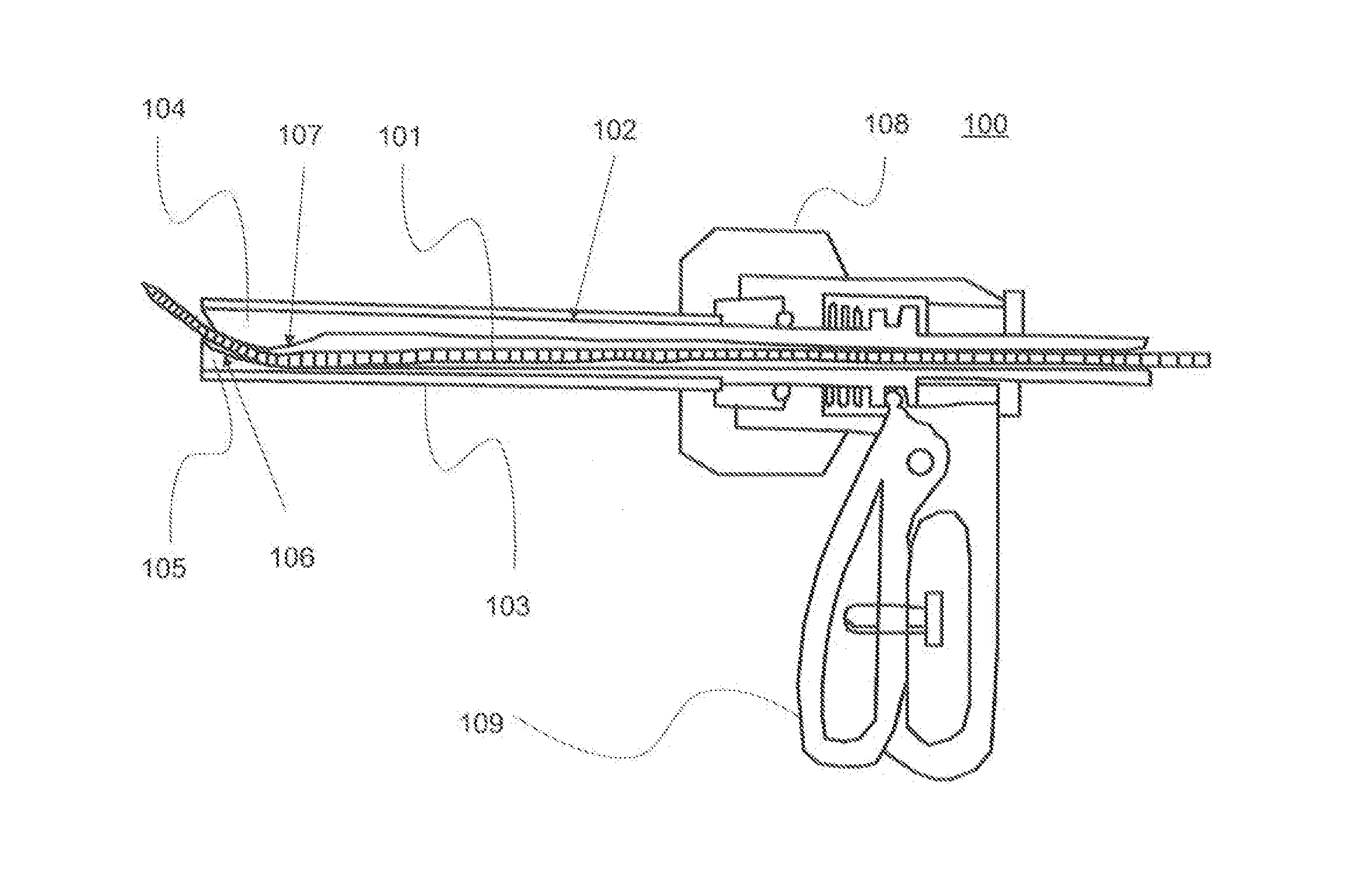
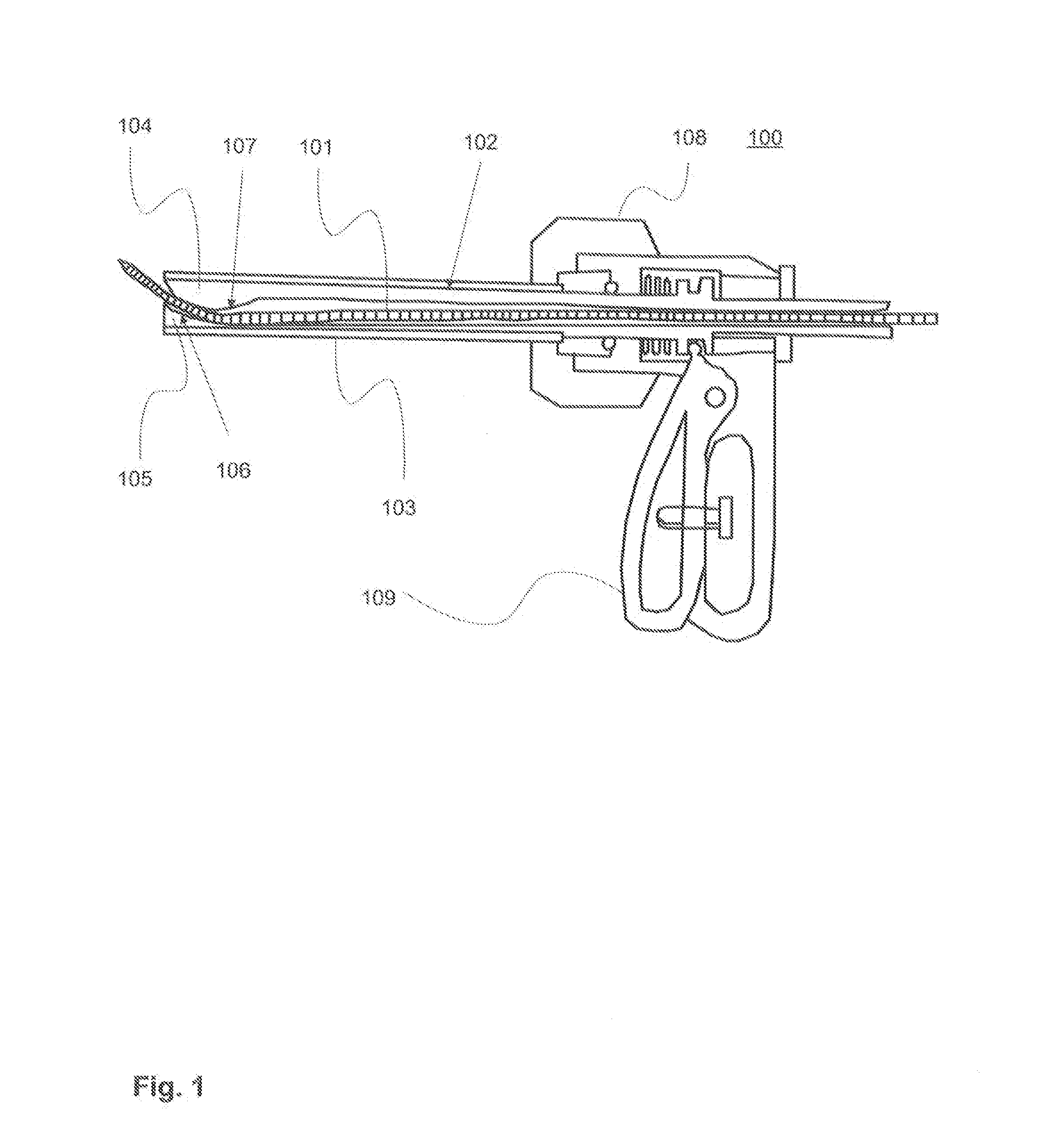
[0030]In the first embodiment, the drill-component shield is tubular and open at the end. In the present case, the term open “end” of the tubular shield refers to its “distal end”, or the point of the shield. This is the end of the shield that is farthest from the user of the drill. In particular, the end in question faces away from the user. Most appropriately, the open portion of the end in question faces in a direction 180 degrees in the opposite direction compared to the proximal end of the tubular shield (i.e. the end closest to the user).

[0031]In a preferred embodiment, the shield is equally thick over the entire area of the tubular part, including the end, i.e. it has a constant outer diameter throughout.

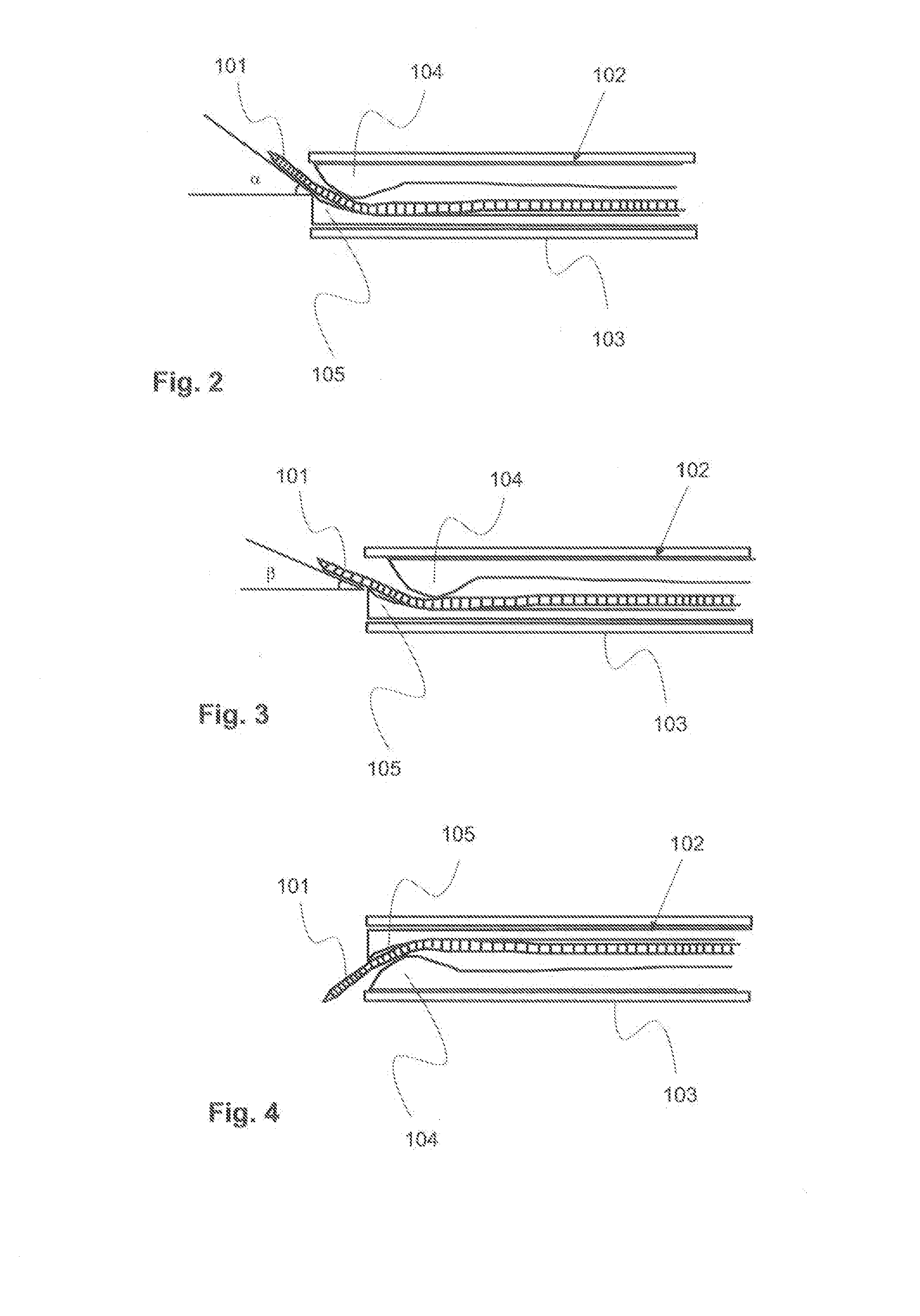
[0032]The distal end is arranged to be pushed into a drill hole or channel made in the bone, which means that, at it, the external diameter of the drill-component shield is smaller than the internal diameter of the drill hole or channel in question. The external diameter of t...

second embodiment

[0039]In the bone drill, the guide arrangement can be changed in order to change the turning angle. The turning angle is then specific to each guide arrangement.

third embodiment

[0040]In the bone drill, the guide arrangement is inside the drill-component shield and, in the guide arrangement, there is a slide component and a counter-component, and the drill component is arranged to run between the slide component and the counter-component, in such a way that they alter the turning angle of the drill component.


PUM


Abstract

A bone drill for medical operations is provided. In the bone drill, there is an elongated drill component), which is manufactured from a superelastic material, and an essentially straight drill-component shield, which is hollow. According to the invention, at the end of the drill-component shield there is a guide arrangement for selecting for the drill component a turning angle relative to the drill-component shield, and once the drill component has run through the guide part, the superelastic properties of its material return it to its original shape and the drill component is then is a position, in which it can be used to drill in the direction of the turning angle.

Description

FIELD OF INVENTION[0001]The invention relates to a bone drill for medical operations, in which bone drill there is an elongated drill component, which is manufactured from a superelastic material, and an essentially straight drill-component shield, which is hollow.BACKGROUND OF THE INVENTION[0002]In many medical operations holes or channels in bone are required. These are used, for example, for inserting screws, for removing a damaged or diseased part of a bone, or for inserting a medicament or implant in a bone. There are many different bone drills for these purposes.[0003]Generally, it is difficult to guide a drill inside a bone. It is even more difficult if a curve must be made in the channel or hole.[0004]For drilling, drills have been developed, in which components made from a superelastic material are used as the drilling part. A piece made from a superelastic material seeks to return to its original shape. One material widely used in medical devices is nitinol, an alloy of ti...

Claims


Application Information

Patent Timeline
Patent Type & Authority Applications(United States)
IPC IPC(8): A61B17/16
CPCA61B17/1617A61B17/1631A61B2017/00867A61B17/17G01B7/30A61B17/1642A61B6/512A61B6/51A61B6/06A61B6/4452A61B6/587
Inventor LEHENKARI, PETRINYKANEN, ARTO
Owner UNIV OF OULU
Why Eureka
Try Eureka