Liquid crystal display device and polymer for alignment film materials

a liquid crystal display device and alignment film technology, applied in the field of liquid crystal display devices and polymers of alignment film materials, can solve the problems of generating image sticking, reducing the uniformity of alignment, and insufficient homopolymer or copolymer of only the photo-alignment film material (s), so as to suppress the ac image sticking, reduce the cost, and drive

Active Publication Date: 2013-05-02
SHARP KK
View PDF3 Cites 3 Cited by
  • Summary
  • Abstract
  • Description
  • Claims
  • Application Information

AI Technical Summary

Benefits of technology

The present invention relates to a liquid crystal display device that can suppress the generation of AC image sticking. The invention involves a special alignment film material that can control the alignment of liquid crystal molecules in the device. The alignment film material is a copolymer that contains two constitutional units, one of which controls the alignment of liquid crystal molecules in a vertical direction and the other in a horizontal direction. The copolymer is obtained by polymerizing a monomer containing a diamine and an acid anhydride. The use of this special alignment film material can effectively suppress the AC image sticking and stably control the average pretilt angle of the liquid crystal layer in the device. The invention is applicable to various horizontal alignment devices, such as VATN, IPS, and ECB devices.

Problems solved by technology

However, in the photo-alignment technology, which is now being employed instead of the rubbing method, the mechanism for generation of the image sticking is not determined yet, and so a solution for it is not proposed yet.
A homopolymer or copolymer of only the photo-alignment film material (s) is not enough to solve particularly the image sticking in AC mode.
In addition, according to an alignment film in which a conventional photofunctional group-containing vertical photo-alignment film and a conventional vertical alignment film are blended, uniformity of alignment is significantly reduced because a density of the photofunctional group-containing vertical photo-alignment film is reduced, and further, the alignment film can not provide liquid crystals with pretilt angles and so the pretilt angle hardly changes from 90°.
So such a film is not enough to suppress the image sticking in AC mode.

Method used


Image

  • Liquid crystal display device and polymer for alignment film materials
  • Liquid crystal display device and polymer for alignment film materials
  • Liquid crystal display device and polymer for alignment film materials

Examples


embodiment 1

[0102]The present Embodiment is mentioned in the following order: 1. alignment film material; 2. preparation method of alignment film; 3. basic operations of liquid crystal display device; 4. production method of liquid crystal display device; and 5. evaluation test of AC image sticking

1. Alignment Film Material

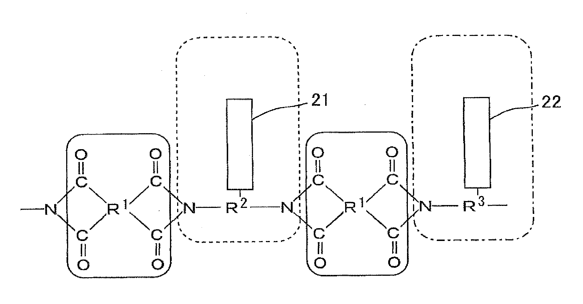
[0103]The alignment film material of the present Embodiment includes a polymer essentially containing a first constitutional unit and a second constitutional unit. The first constitutional unit exhibits a property of controlling alignment of liquid crystal molecules by photoirradiation. The second constitutional unit exhibits a property of controlling alignment of liquid crystal molecules regardless of photoirradiation. More particularly the first constitutional unit has a side chain containing a photofunctional group, and the second constitutional unit has a side chain containing a vertical alignment functional group. Thus, the side chain of the second constitutional unit co...


PUM

PropertyMeasurementUnit
pretilt angleaaaaaaaaaa
bending deformationaaaaaaaaaa

Abstract

A liquid crystal display device suppresses generation of image sticking in AC mode. A liquid crystal display device comprises an alignment film arranged on at least one of a pair of substrates. The alignment film comprises a polymer containing a first constitutional unit and a second constitutional unit. The first constitutional unit controls alignment of the liquid crystal molecules by photoirradiation. The second constitutional unit controls alignment of the liquid crystal molecules regardless of photoirradiation.

Description

[0001]This application is a continuation of U.S. patent application Ser. No. 12 / 593,121, filed 25 Sep. 2009, which is the U.S. national phase of International Application No. PCT / JP2008 / 053315, filed 26 Feb. 2008, which designated the U.S. and claims priority to Japanese Patent Application No. 2007-080289, filed 26 Mar. 2007, the entire contents of each of which are hereby incorporated by reference.TECHNICAL FIELD[0002]The present invention relates to a liquid crystal display device and a polymer for alignment film materials. More particularly, the present invention relates to a liquid crystal display device with wide viewing angle characteristics, preferably used in planar displays that are used by many people, such as a PDA, a PC, a WP, amusement equipment, a teaching machine, and a TV device, or in a display board, a display window, a display door, a display wall, etc., each utilizing a shutter effect of liquid crystal. Further, the present invention relates to a polymer for alig...

Claims


Application Information

Patent Timeline
Patent Type & Authority Applications(United States)
IPC IPC(8): G02F1/1333
CPCG02F1/133711G02F1/133723G02F1/133362G02F2001/133746G02F2001/133757G02F1/133788G02F1/133746G02F1/133757
Inventor TERASHITA, SHINICHIMIYAKE, ISAMUMIYACHI, KOICHITERAOKA, YUKO
Owner SHARP KK
Why Eureka
Try Eureka