Method and device for monitoring biomechanical properties of the eye
a biomechanical and eye technology, applied in the field of eye biomechanical properties monitoring, can solve the problems of burdensome and expensive, unable to adapt and periodically adjust the system, and achieve the effect of less calibration efforts
- Summary
- Abstract
- Description
- Claims
- Application Information
AI Technical Summary
Benefits of technology
Problems solved by technology
Method used
Image
Examples
example 1
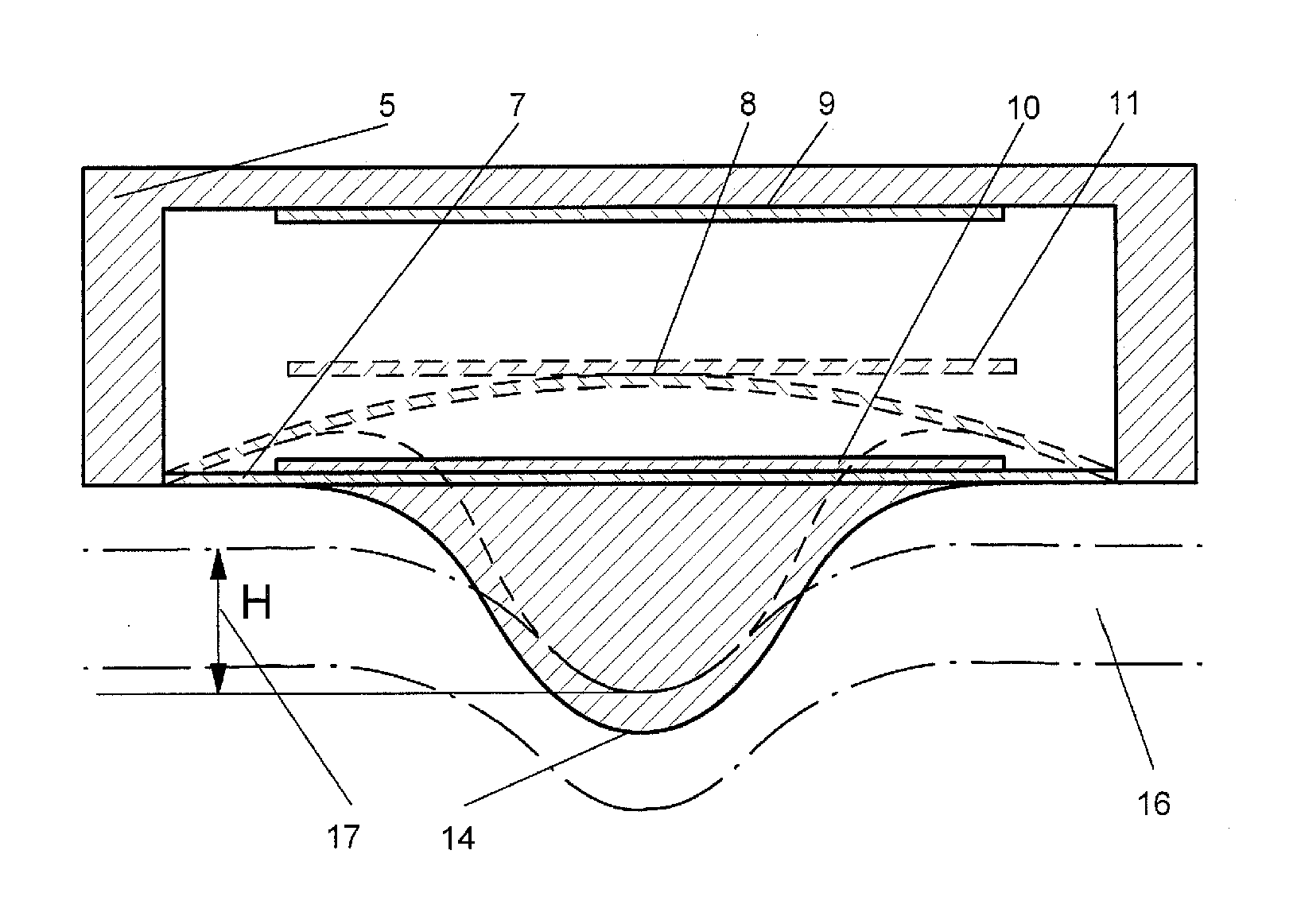
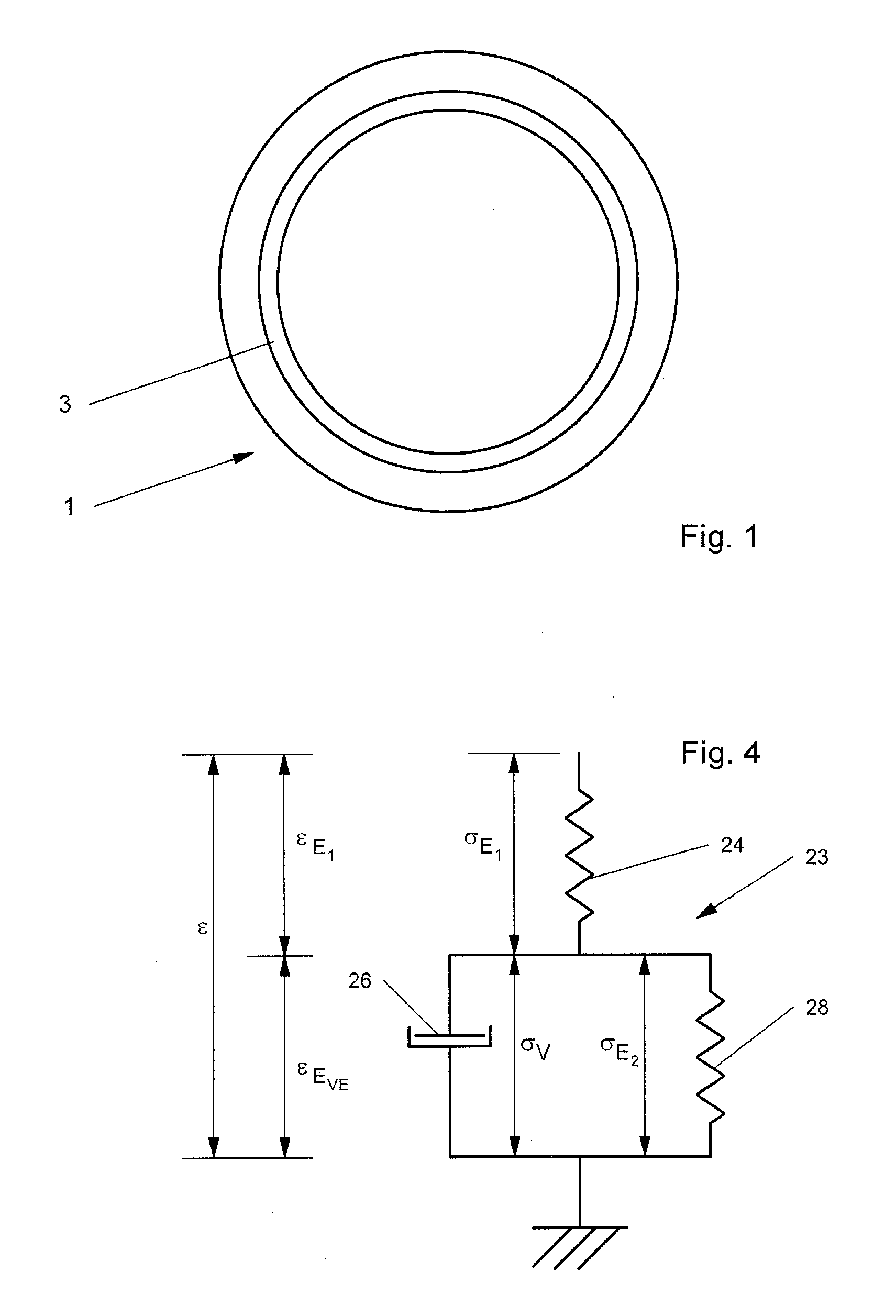
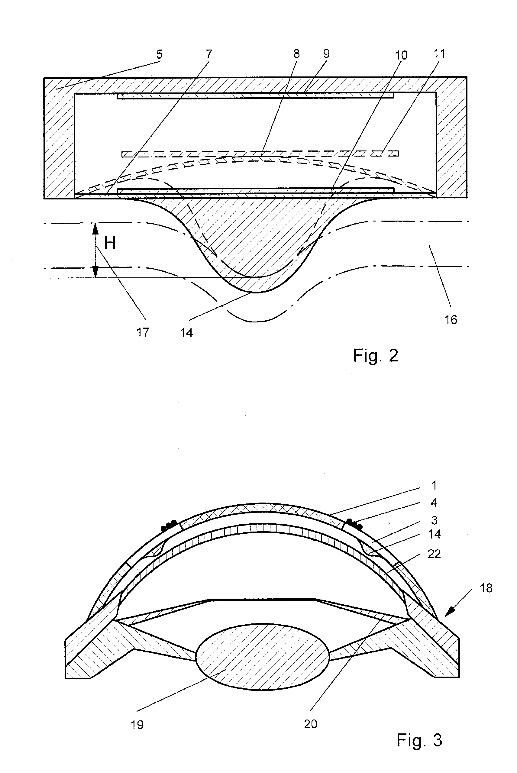
[0057]In order to determine the characteristic values of the hysteresis curve 29 of FIG. 5, the finding is used that the acceleration values during opening (aopen) and closing (aclose) of the lid can be derived from the delay between occurrence of maximal force, corresponding to the closed lid, and the time when the force is zero again, i.e. the lid is opened to a degree that the knob 14 does no more exert a sensible force on the cornea. As explained above, the indentation depth H is then accessible by interpolating the position of the lid using the general equation
slid=½a t2+v0 t+slid0 (6)
with[0058]a: the acceleration of the lid[0059]slid: position of the lid at time t[0060]slid0:position of the lid at t=0: on closing: slid0=0; on opening: slid0=final position of the when closed, i.e. at tIOP0.[0061]t: time[0062]v0: the velocity of the lid at time t =0 defined as the moment when the knob 14 hits the cornea 22 on lid closing; on lid opening: v0=0
[0063]For the application of this e...
example 2
[0106]In order to avoid the computational effort of Example 1, the sensor can be modified the way that at least two segments of distinctly different height Hknob(i), i≧2, are present, Preferably, the segmentation is at least mirror-symmetrical in view of the about mirror-symmetrical movement of the lids.
[0107]FIG. 8 shows an arrangement with two large segments S051 which constitutes the first sensor. Between them two smaller segments S153 are provided, constituting sensor 2. They are characterized by a knob significantly lower than the knob of S0.
[0108]For the data transfer, two antennas 55, 56 are provided for sensor 51 resp. 53, each extending over the whole periphery.
[0109]However, the antenna / sensor capacitor arrangements are responsive to different frequencies so that the sensors are capable to furnish data independently and without additional measures for avoiding conflicts.
[0110]Besides the antennas 55, 56, FIG. 9 also shows the differing heights Hknob,s0 58 and Hknob,s1 59.
[...
example 3
[0118]The knob is provided with a transition 70. In FIG. 12, the transition is a transition to a broader knob shape. In other terms, from the apex 72 to the transition 70, the shape of the knob corresponds to a small knob, and from transition 70 down to the membrane 7, the shape of the basis 71 corresponds to a bigger knob.
[0119]When the knob 14 is pressed on the cornea 16, the signals obtained are those as if the knob has the shape of the small knob (portion 73 in FIG. 13). If the indentation increases, the cornea gets in touch with the transition 70 at time ttrigger0 74. As the contact zone is stepwise increased, also the force signal of the sensor shows a step increase 74. Afterwards, the signal 75 merely corresponds to that of a virtual bigger knob.
[0120]During opening of the eye, the same occurs in the inverse sense at ttrigger1 75: The force signal shows a sharp decay 77 when the cornea no more touches the broader basis 71.
[0121]As shown in FIG. 14, the same effect may be obta...
PUM
 Abstract
Description
Claims
Application Information
 - R&D
- Intellectual Property
- Life Sciences
- Materials
- Tech Scout
- Unparalleled Data Quality
- Higher Quality Content
- 60% Fewer Hallucinations
Browse by: Latest US Patents, China's latest patents, Technical Efficacy Thesaurus, Application Domain, Technology Topic, Popular Technical Reports.
© 2025 PatSnap. All rights reserved.Legal|Privacy policy|Modern Slavery Act Transparency Statement|Sitemap|About US| Contact US: help@patsnap.com


