
Deployment methods and mechanisms for minimally invasive implantation of heart contacting cardiac devices

a technology of contacting cardiac devices and deployment methods, which is applied in the field of mechanical interfaces, can solve problems such as difficult to recognize the development of persistent underlying disease, remodeling dramatically alters the mechanical environment, and remodeling processes

Active Publication Date: 2013-04-25
TEXAS A&M UNIVERSITY +1
View PDF12 Cites 21 Cited by
  • Summary
  • Abstract
  • Description
  • Claims
  • Application Information

AI Technical Summary

Benefits of technology

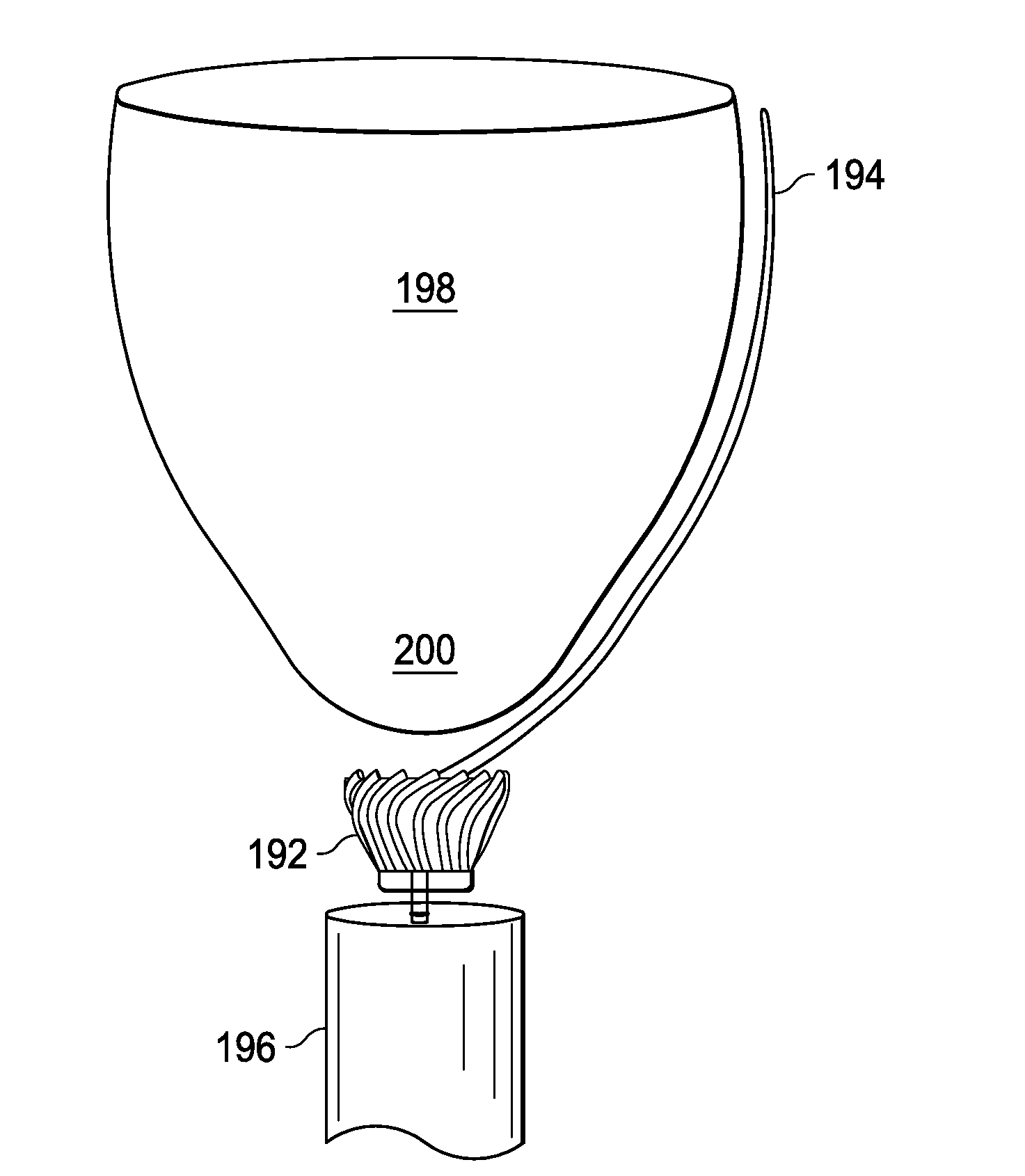
The present invention provides a device that helps to stabilize the pericardium, which is a membrane around the heart. This device has a housing with two openings and a framework of extendable wire loops that can be extended from the first opening to help separate the pericardial sac from the heart. The use of flaring can also be employed to further separate the pericardial sac from the heart.

Problems solved by technology

Due to the effectiveness of these compensatory mechanisms, it is often difficult to recognize the development of persistent underlying disease, as the patient may appear asymptomatic with respect to metrics such as ejection fraction and cardiac output.
Left ventricular remodeling dramatically alters the mechanical environment, which in turn influences growth and remodeling processes.
Interestingly, abnormal cardiac kinematics is often considered a symptom of heart failure when in actuality it is likely that aberrant motion is a primary contributing factor to the aberrant growth and remodeling i.e., cellular responses to the pathologic mechanical factors lead to further pathologic remodeling and a positive feedback loop emerges such that eventually a threshold is reached wherein the neurohormonal compensatory mechanisms activated to maintain homeostasis are no longer sufficient to deter further progression of the disease.
Consequently, treatment strategies that fail to remedy the aberrant mechanical environment become increasingly ineffective as the disease progresses.
In addition, other therapies like drugs, biventricular pacing, stem cell therapies, blood contacting assist devices, surgical manipulations, or passive stents and constraints typically off-load the heart and thus only modulate the strain pattern indirectly.
The foregoing problems have been recognized for many years and while numerous solutions have been proposed, none of them adequately address all of the problems.

Method used


Image

  • Deployment methods and mechanisms for minimally invasive implantation of heart contacting cardiac devices
  • Deployment methods and mechanisms for minimally invasive implantation of heart contacting cardiac devices
  • Deployment methods and mechanisms for minimally invasive implantation of heart contacting cardiac devices

Examples


Embodiment Construction

[0036]While the making and using of various embodiments of the present invention are discussed in detail below, it should be appreciated that the present invention provides many applicable inventive concepts that can be embodied in a wide variety of specific contexts. The terminology used and specific embodiments discussed herein are merely illustrative of specific ways to make and use the invention and do not delimit the scope of the invention.

[0037]To facilitate the understanding of this invention, a number of terms are defined below. Terms defined herein have meanings as commonly understood by a person of ordinary skill in the areas relevant to the present invention. Terms such as “a”, “an” and “the” are not intended to refer to only a singular entity, but include the general class of which a specific example may be used for illustration. The terminology herein is used to describe specific embodiments of the invention, but their usage does not delimit the invention, except as out...


PUM


Abstract

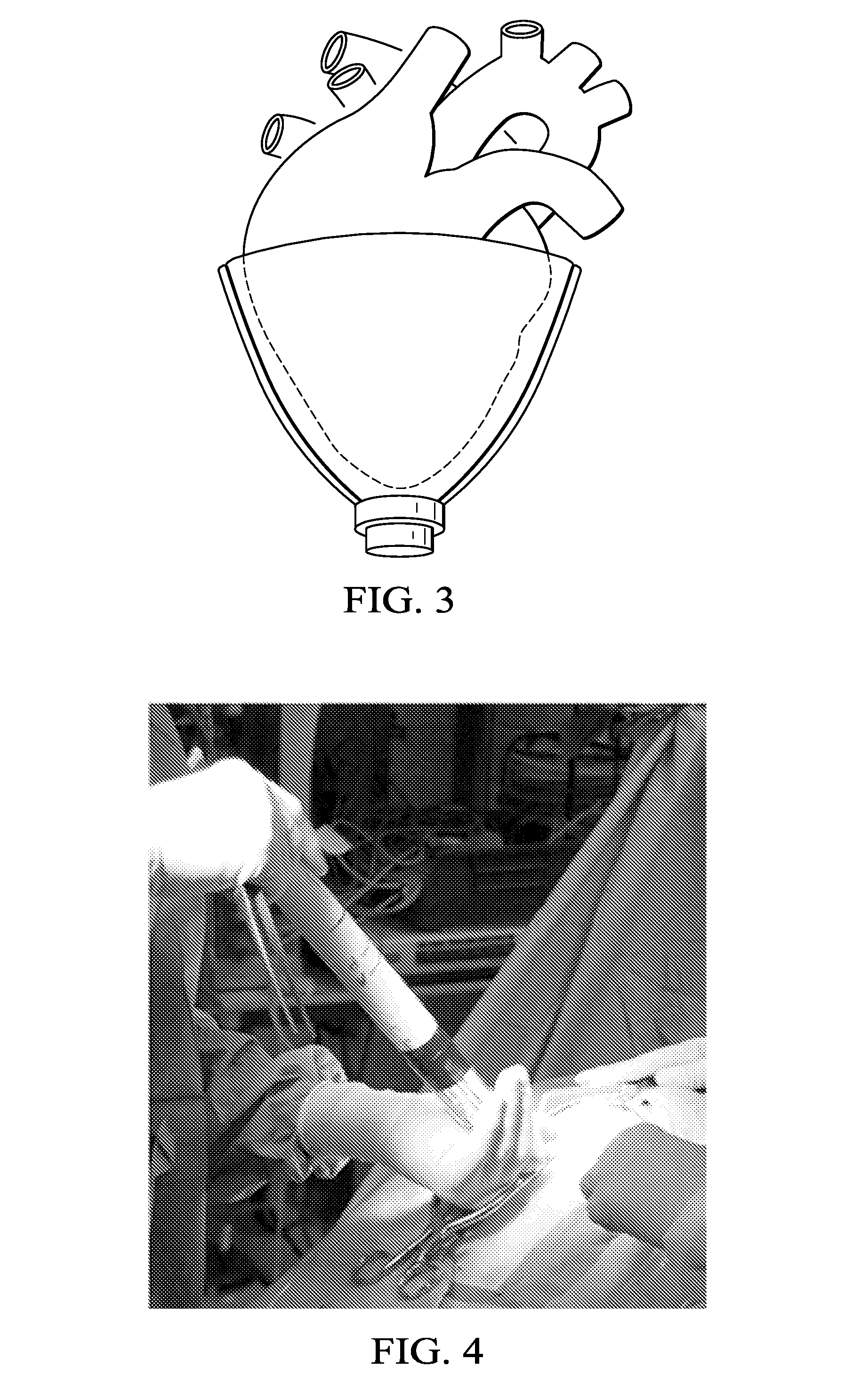
The present invention provides methods, systems, kits, and devices that aid in the positioning of a direct cardiac compression device about the heart.

Description

CROSS-REFERENCE TO RELATED APPLICATIONS[0001]This application claims priority to U.S. Patent Application Ser. No. 61 / 548,584 files on Oct. 18, 2011 and is related to U.S. patent application Ser. No. 11 / 400,148, filed Apr. 6, 2006, which claims priority to U.S. Provisional Patent Application Ser. No. 60 / 668,640, filed Apr. 6, 2005, and is related to U.S. patent application Ser. No. 10 / 870,619, filed Jun. 17, 2004, the contents of which are all incorporated by reference herein in their entirety.STATEMENT OF FEDERALLY FUNDED RESEARCH[0002]This invention was made with U.S. Government support under Contract Numbers 1 R42 HL080759-01 and 4 R42 HL080759-02 awarded by the NIH and Contract Number IIP-0912711 awarded by the NSF. The government has certain rights in this invention.TECHNICAL FIELD OF THE INVENTION[0003]The present invention relates in general to a mechanical interface for the heart of a patient to improve its pumping function, and, more particularly, modulate contraction strain...

Claims


Application Information

Patent Timeline
IPC IPC(8): A61B1/32
CPCA61F2/2481A61B1/32A61M60/865A61M60/289A61M60/191A61M60/468
Inventor CRISCIONE, JOHN C.HARRISON, LEWIS D.MORENO, MICHAEL R.BOLCH, CHRISTINA M.ROBBINS, DENNIS I.BISWAS, SAURABH
Owner TEXAS A&M UNIVERSITY
Learn More