
Refrigerator

Inactive Publication Date: 2013-04-11
LG ELECTRONICS INC
View PDF8 Cites 14 Cited by
  • Summary
  • Abstract
  • Description
  • Claims
  • Application Information

AI Technical Summary

Benefits of technology

The refrigerator has a specific design that prevents the temperature inside the refrigerating compartment from rising too much. This is achieved by making the part of the refrigerator where the evaporator is located thicker and colder, which affects the temperature of the inside of the refrigerating compartment the least. The evaporator is located on the freezing compartment to keep the barrier (which is the area around the refrigerator) thin while still insulating well. Additionally, there is a space between the evaporator and the blowing unit that improves the flow of cold air and helps to keep the refrigerating compartment cool. The design is simple and easy to understand.

Problems solved by technology

The side by side-type refrigerator among such refrigerators is configured to have an evaporator mounted on the rear side of the refrigerating compartment and / or the freezing compartment to supply cold air to the refrigerating compartment and the freezing compartment, but there is a problem in that the interior volume of the refrigerator is decreased by the space occupied by the mounting of the evaporator.
However, in such a refrigerator, the heat insulation of the barrier on which the evaporator and the cold air circulation fan are disposed is not made, so that there is a problem in that a refrigerating compartment is excessively cooled.
Furthermore, there is a problem in that the circulation of the cold air flowing in a narrow space within the barrier is not smooth.

Method used


Image

  • Refrigerator
  • Refrigerator
  • Refrigerator

Examples


first embodiment

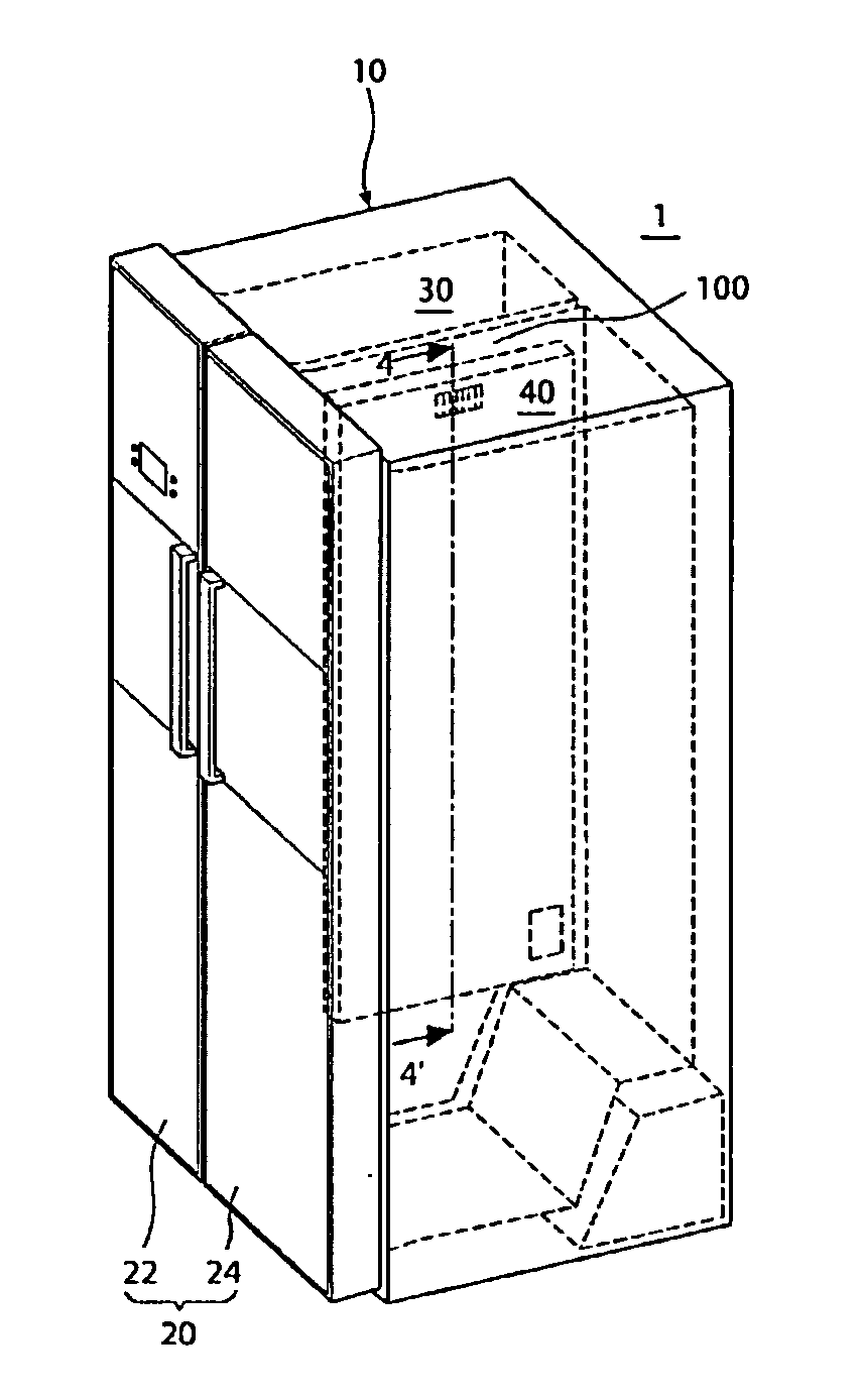
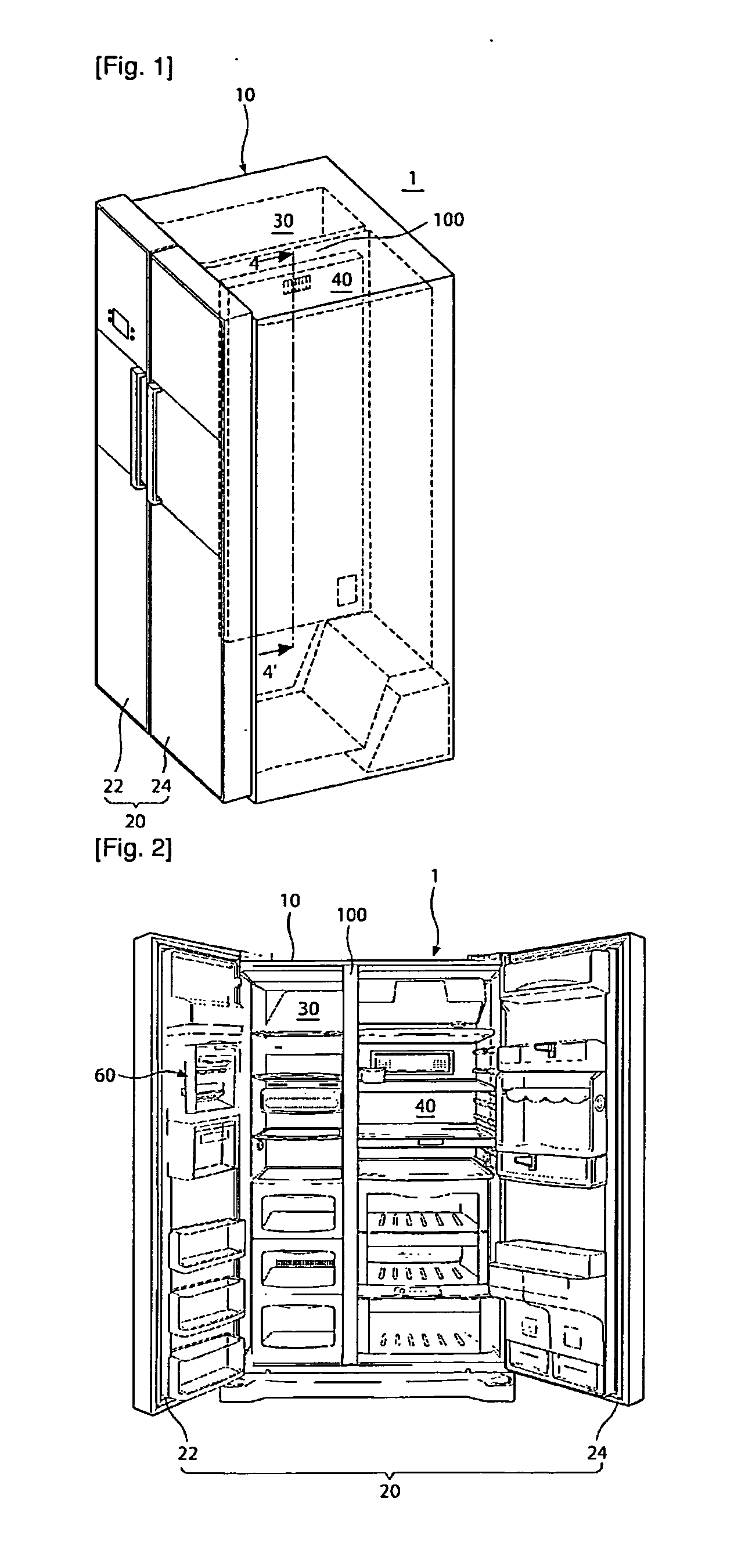
[0116]FIG. 1 is an exterior perspective view of a refrigerator according to the present invention; FIG. 2 is a front perspective view showing the internal structure of the refrigerator;

[0117]Referring to FIGS. 1 and 2, the exterior shape of the refrigerator 1 according to an embodiment of the present invention is formed by a cabinet 10 defining a storage space and a door 20 to open and close the storage space.

[0118]The cabinet 10 is divided into left and right sides by a barrier 100 to define a refrigerating compartment 40 and a freezing compartment 30 respectively. The refrigerating compartment 40 and the freezing compartment 30 are configured to have a plurality of drawers and shelves therein and to preserve various foods therein. The door 20 is configured to include a refrigerating compartment door 24 and a freezing compartment door 22 for respectively opening and closing the refrigerating compartment 40 and the freezing compartment 30. Furthermore, the refrigerating compartment ...

second embodiment

[0171]FIG. 10 is an exploded perspective view of a barrier according to the present invention. In addition, FIGS. 7 and 8 are perspective views showing the shape of an upper cover according this embodiment of the present invention. FIGS. 9 and 10 are perspective views showing the shape of a lower cover according this embodiment of the present invention.

[0172]In the second embodiment of the present invention, same structures as the structures of the first embodiment as described above are denoted by the same reference numerals and therefore, the detailed description of the corresponding structures will be omitted.

[0173]The barrier cover 400 according to the second embodiment if the present invention is configured to include an upper cover 410 and a lower cover 420.

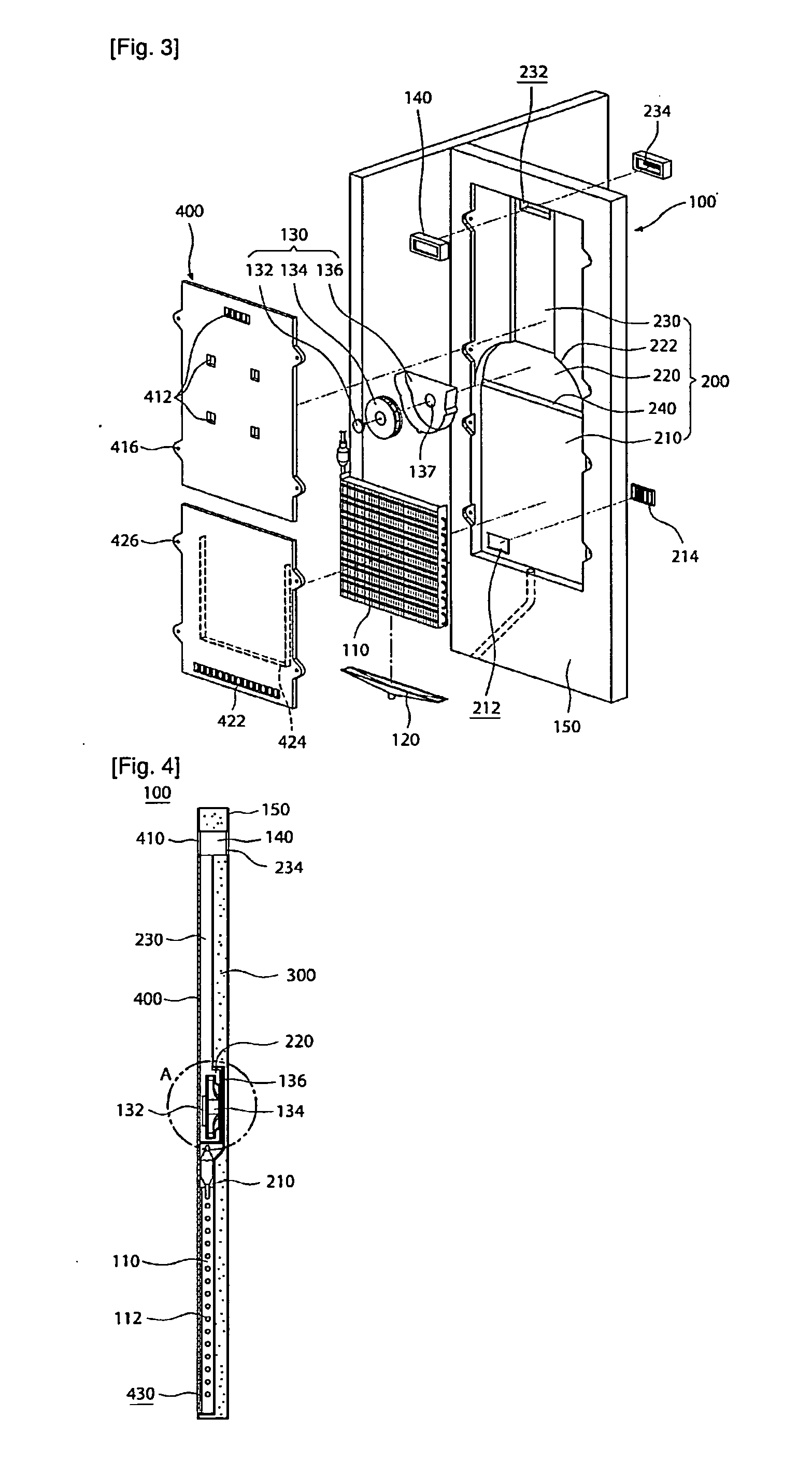
[0174]Referring to FIGS. 10 to 12, the depression part 200 depressed on the freezing compartment 30 is formed in the barrier 100. The depression part 200 may include an evaporator accommodating part 210 in which the evapora...

third embodiment

[0200]FIG. 15 is an exploded perspective view of a barrier according to the present invention. FIG. 16 is a front view showing the shape of the depression part of the barrier. FIG. 17 is a perspective view taken along line 17-17′ of FIG. 16.

[0201]In the third embodiment of the present invention, same structures as the structures of the first embodiment as described above are denoted by the same reference numerals and therefore, the detailed description of the corresponding structures will be omitted.

[0202]A foamed heat insulator 300 is provided in the barrier 100 according to the third embodiment of the present invention and a separate heat insulator 500 is further provided in the depression part 200 formed in the barrier 100.

[0203]Referring to FIGS. 15 to 17, the external shape of the barrier 100 is formed by a casing 150 defining the internal spaces of the refrigerating compartment 40 and the freezing compartment 30 and foaming liquid is filled in the inside of the casing 150 ther...


PUM


Abstract

Disclosed herein is a refrigerator including: a cabinet configured to define a storage space; a barrier configured to divide the storage space into a refrigerating compartment and a freezing compartment and having an heat insulator therein; a depression part formed to be depressed in the barrier for the freezing compartment and configured to accommodate an evaporator and a blowing unit; and a barrier cover configured to shield the depression part for the freezing compartment, wherein the depression part includes an evaporator accommodating part configured to accommodate the evaporator, a blowing unit accommodating part formed to be stepped on a upper side of the evaporator accommodating part and configured to accommodate the blowing unit.

Description

TECHNICAL FIELD[0001]The present invention relates to a refrigerator.BACKGROUND ART[0002]Generally, a refrigerator is consumer electronics that can store food at low temperature. The refrigerator uses cool air generated by heat exchange with a refrigerant circulating a freezing cycle to cool the storage space, such that it is configured to store the stored food at an optimum state.[0003]The refrigerator tends to increase more and more in its size and to have multi-functions as dietary life changes and users' taste is diversified, and the structure thereof is also diversified according to the configuration of the storage space.[0004]Generally, the storage space inside the refrigerator is divided by a barrier to form a refrigerating compartment and a freezing compartment, and the structure thereof may be variously configured according to the arrangement of the refrigerating compartment and the freezing compartment.[0005]In particular, a side by side-type refrigerator among such refrig...

Claims


Application Information

Patent Timeline
IPC IPC(8): F25D17/06F25B39/02
CPCF25D17/065F25B39/02F25D2400/06F25D23/063F25D2317/0681
Inventor CHOI, BONGJUNYOU, GILJAESONG, MINHOKIM, JUHYUNKIM, DONGSEOK
Owner LG ELECTRONICS INC
Learn More