Wire winding device structure
- Summary
- Abstract
- Description
- Claims
- Application Information
AI Technical Summary
Benefits of technology
Problems solved by technology
Method used
Image
Examples
Embodiment Construction
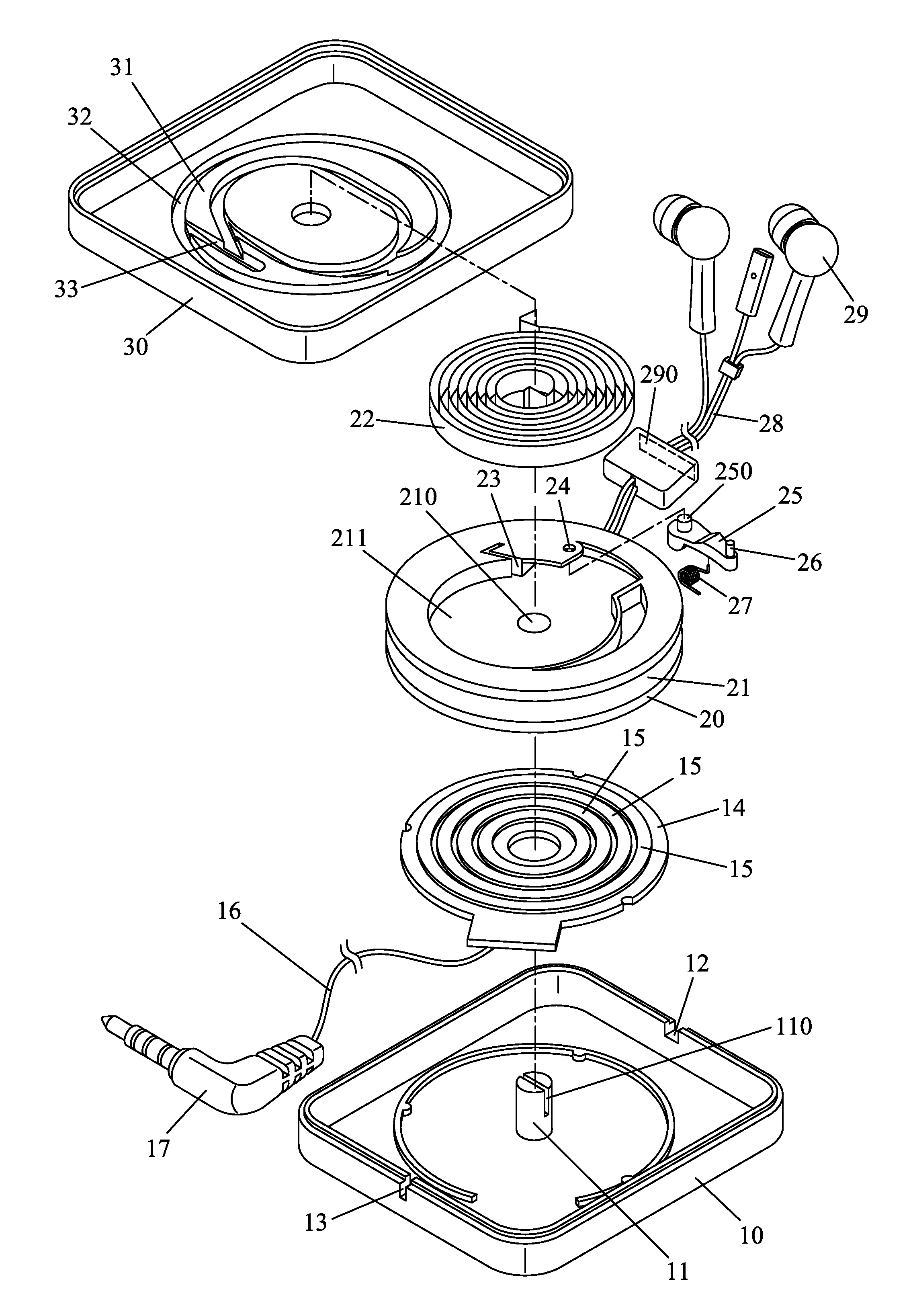
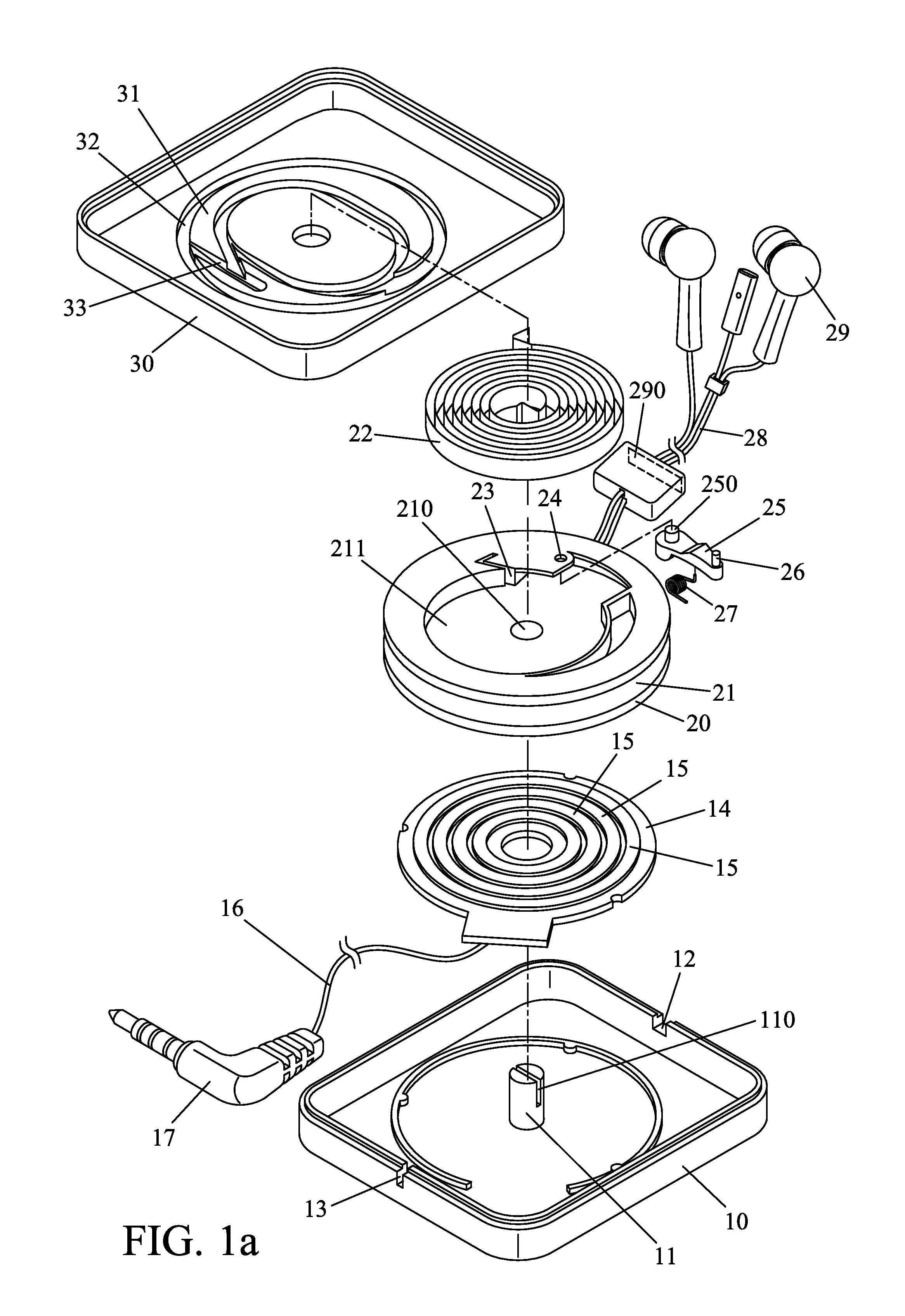
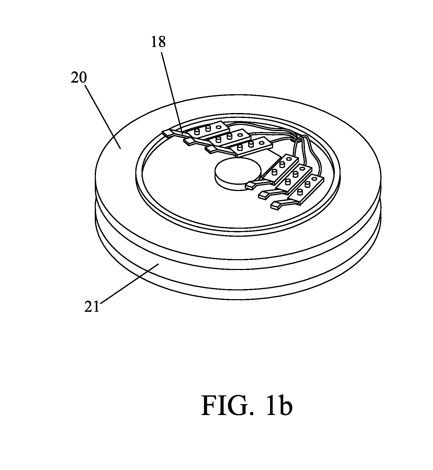
[0005]With reference to FIG. 1a, 1b, 2, 3, 4, 5, 6, the wire winding device of the present device comprising:
[0006]a box body 10, insulating disc 14, rotary disc 20, volute spring 22, upper cover 30; wherein
[0007]said box body 10 has axle 11 with transverse groove 110, groove 13 and wire outlet 12 on the wall;
[0008]said insulating disc has several spaced metal annular tablet assembled in box body 10, a signal input wire 16 with plug 17, said signal input wire 16 being one end poke out through groove 13 of box body 10 and the other end electric welded to the bottom of metal annular tablet 15 of insulating disc 14;
[0009]said rotary disc 20 has axial hole 210 in the center which rotatable shrinking on the axle 11 of box body 10, a wire winding annular groove 21 on its perimeter for winding signal output wire 28, several metal spring piece 18 correspondingly contacting to each metal annular tablet 15 of insulating disc, wire 28 winding on rotary disc 20 being one end electric welded to ...
PUM
 Abstract
Description
Claims
Application Information
 - R&D
- Intellectual Property
- Life Sciences
- Materials
- Tech Scout
- Unparalleled Data Quality
- Higher Quality Content
- 60% Fewer Hallucinations
Browse by: Latest US Patents, China's latest patents, Technical Efficacy Thesaurus, Application Domain, Technology Topic, Popular Technical Reports.
© 2025 PatSnap. All rights reserved.Legal|Privacy policy|Modern Slavery Act Transparency Statement|Sitemap|About US| Contact US: help@patsnap.com


