
Method for identifying touch object

a touch object and stylus technology, applied in the field of identifying a stylus on a touch panel, can solve the problems of difficult to decide a fixed noise threshold value, and the finger sensed signals are not easy to be incorrectly identified as those of other touch objects

Active Publication Date: 2013-03-28
ELAN MICROELECTRONICS CORPORATION
View PDF2 Cites 26 Cited by
  • Summary
  • Abstract
  • Description
  • Claims
  • Application Information

AI Technical Summary

Benefits of technology

The present invention provides a method for identifying touch objects on a touch panel using a stylus, while being immune to the influence of noises generated from the liquid crystal module (LCM). The method utilizes a predetermined range of slopes for noise signals and compares it with the slopes of the sensed signals of the stylus. Sensed signals with higher slopes are picked up and their capacitance variation values are compared with those of adjacent sensed signals to determine if they are greater. This allows the method to identify the positions on the touch panel touched by the stylus and define the sensed points. The method is thus able to accurately identify the positions on the touch panel that are triggered by the stylus while being immune to the influence of noises generated from the LCM.

Problems solved by technology

However, with reference to FIG. 5B, as the true capacitance variation value of the LCM noise dVRnoise is not a constant, it's difficult to decide a fixed noise threshold value.
Since dVfinger is normally greater than dVstylus and dVnoise, the sensed signals for fingers are not easy to be incorrectly identified as those for other touch objects.

Method used


Image

  • Method for identifying touch object
  • Method for identifying touch object
  • Method for identifying touch object

Examples


first embodiment

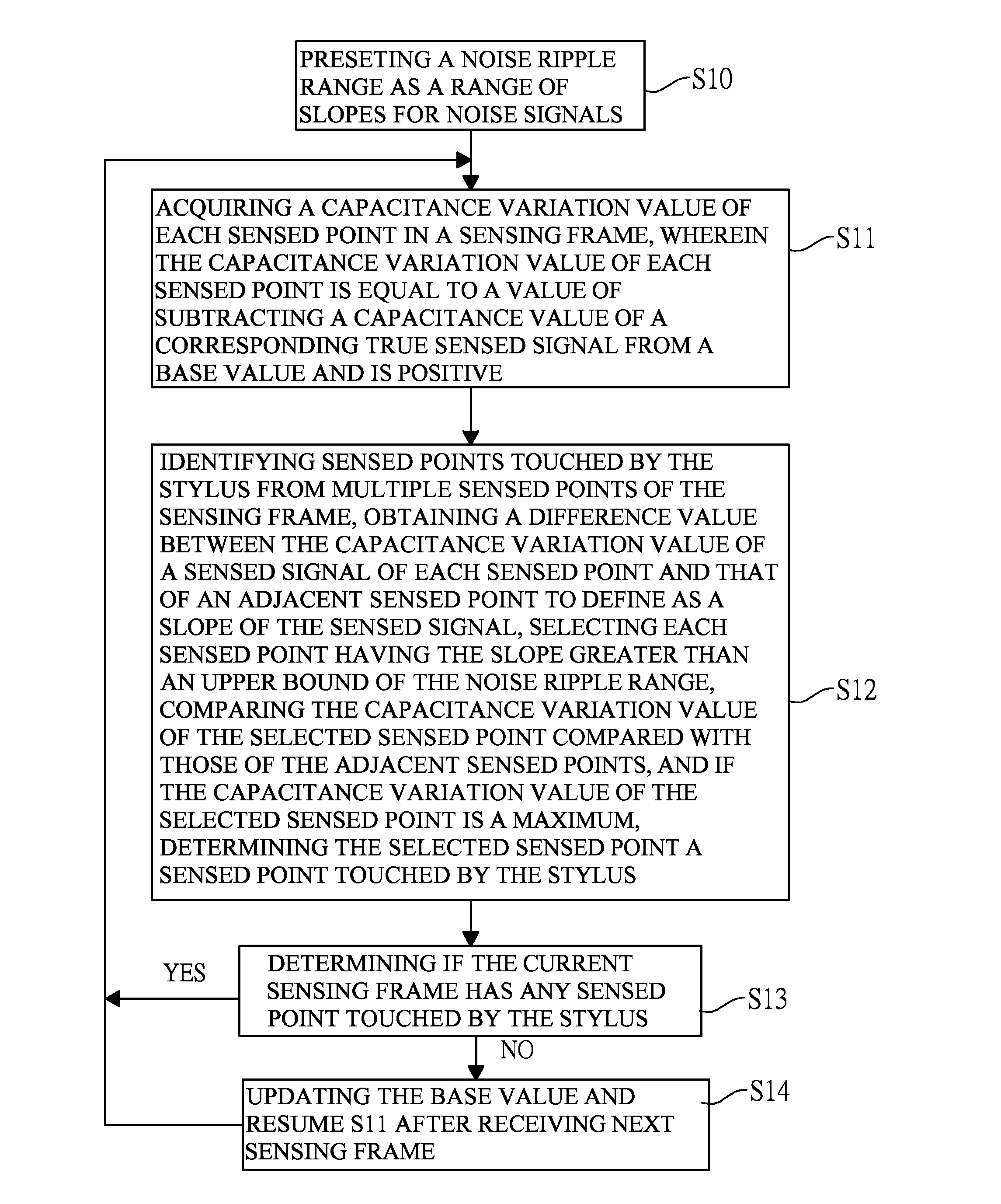
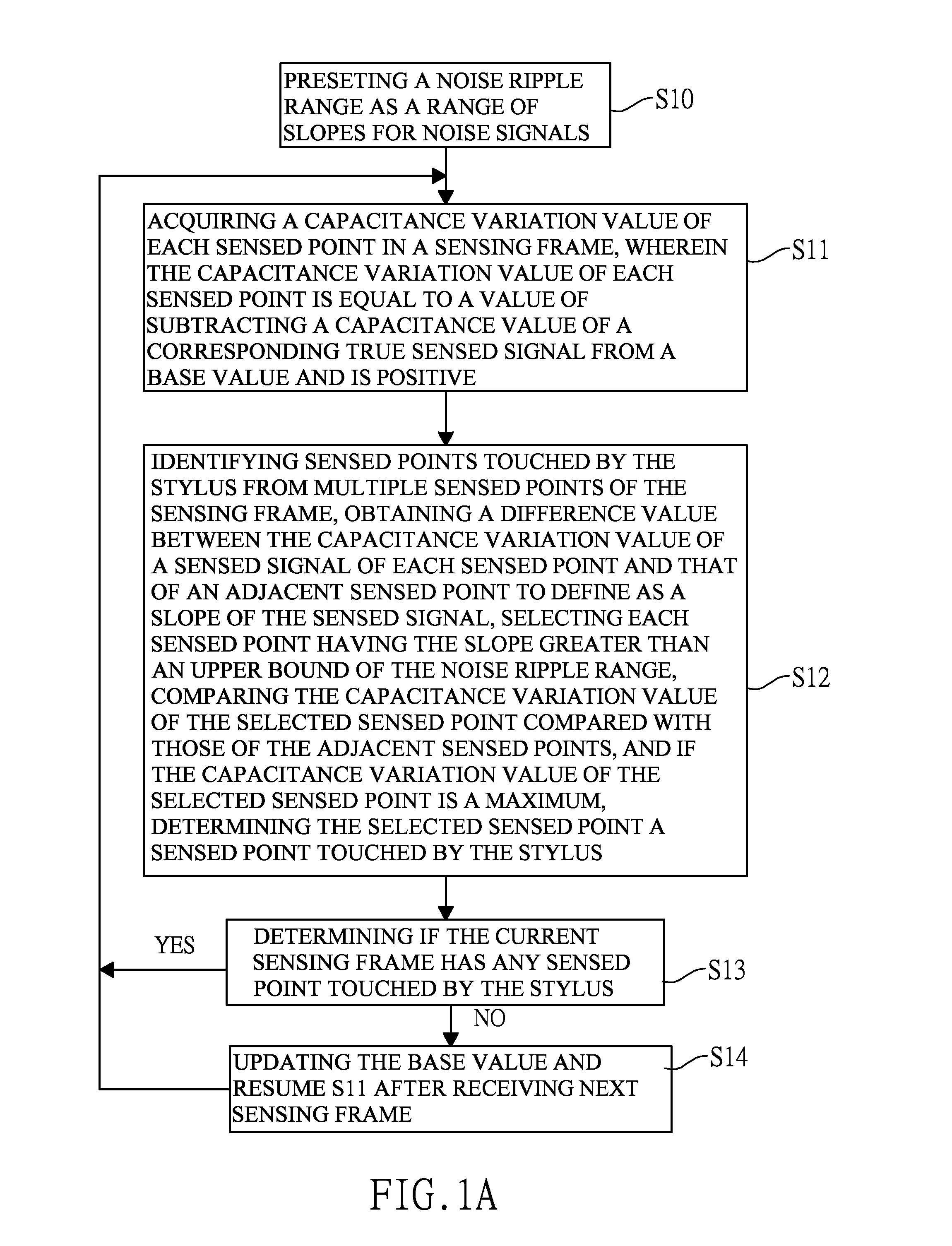
[0029]With reference to FIGS. 1A and 1C, a method for identifying touch object in accordance with the present invention is applied to full-scanning sensing frames and has the following steps.

[0030]Preset a noise ripple range dVRnoise as a range of slopes for noise signals (S10).

[0031]Acquire a capacitance variation value of each sensed point in a sensing frame (S11). The capacitance variation value of each sensed point is equal to a value of subtracting a capacitance value of a corresponding true sensed signal from a base value and is positive.

[0032]Identify sensed points touched by the stylus from multiple sensed points of the sensing frame, obtain a difference value between the capacitance variation value of a sensed signal of each sensed point and that of an adjacent sensed point to define as a slope of the sensed signal, select each sensed point having the slope greater than an upper bound of the noise ripple range dVRnoise, and compare the capacitance variation value of the sel...

second embodiment

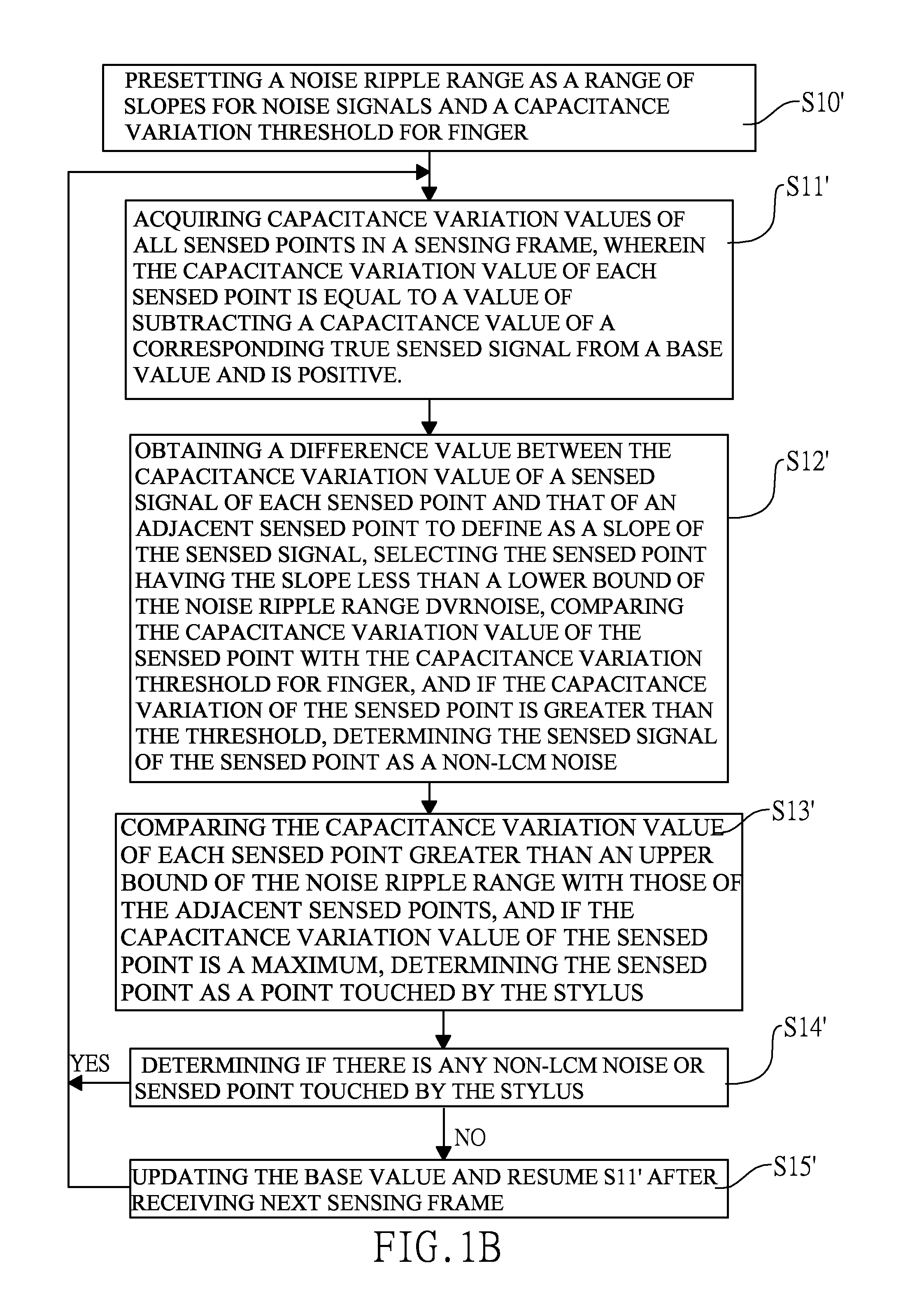
[0034]With reference to FIGS. 1B and 1D, a method for identifying touch object in accordance with the present invention is applied to a touch panel capable of being touched by fingers and a stylus, and has the following steps.

[0035]Preset a noise ripple range dVRnoise as a range of slopes for noise signals and a capacitance variation threshold for finger dVfth (S10′).

[0036]Acquire capacitance variation values of all sensed points in a sensing frame (S11′). The capacitance variation value of each sensed point is equal to a value of subtracting a capacitance value of a corresponding true sensed signal from a base value and is positive.

[0037]Obtain a difference value between the capacitance variation value of a sensed signal of each sensed point and that of an adjacent sensed point to define as a slope of the sensed signal, select the sensed point having the slope less than a lower bound of the noise ripple range dVRnoise, compare the capacitance variation value of the sensed point wit...


PUM


Abstract

A method for identifying touch object has steps of presetting a range of slopes for noise signals, identifying multiple sensed signals, each having a slope higher than the range of slopes for noise signals in a sensing frame, and if the slope of each sensed signal is higher than an upper bound of the range of slopes for noise signals and is higher than each of those of the adjacent sensed signals, determining that the sensed signal is sensed from a corresponding sensed point touched by a stylus. Accordingly, the method can correctly identify a range touched by a stylus from the sensed signals combined with LCM noise signals.

Description

BACKGROUND OF THE INVENTION[0001]1. Field of the Invention[0002]The present invention relates to a method for identifying a stylus on a touch panel and more particularly to a method for distinguishing correct sensed signals of touch objects on a touch panel from noises.[0003]2. Description of the Related Art[0004]When a touch panel is mounted on a liquid crystal module (LCM), noises are generated because of the scanning of the scan lines on the LCM and the noises are hereinafter called LCM noises impacting on positional precision of the touch panel in determining touched points on the touch panel. With reference to FIGS. 5A and 5C, capacitance variation values, dVstylus and dVfinger are equal to a base value subtracted by the capacitance values of true respective sensed signals of a stylus and a finger therefrom, respectively correspond to control ranges for sensing a stylus and fingers on a touch panel, and increase as a result of the LCM noises. If the capacitance variation values...

Claims


Application Information

Patent Timeline
IPC IPC(8): G06F3/033
CPCG06F3/0418G06F3/044
Inventor CHIU, CHING-TING
Owner ELAN MICROELECTRONICS CORPORATION
Learn More