
Proactive cooling control using power consumption trend analysis

a power consumption trend and trend analysis technology, applied in adaptive control, process and machine control, instruments, etc., can solve the problems of increasing the difficulty of cooling servers commonly used in datacenters, consuming more energy than necessary, and consuming a large amount of energy

Active Publication Date: 2013-03-21
LENOVO GLOBAL TECH INT LTD
View PDF12 Cites 54 Cited by
  • Summary
  • Abstract
  • Description
  • Claims
  • Application Information

AI Technical Summary

Benefits of technology

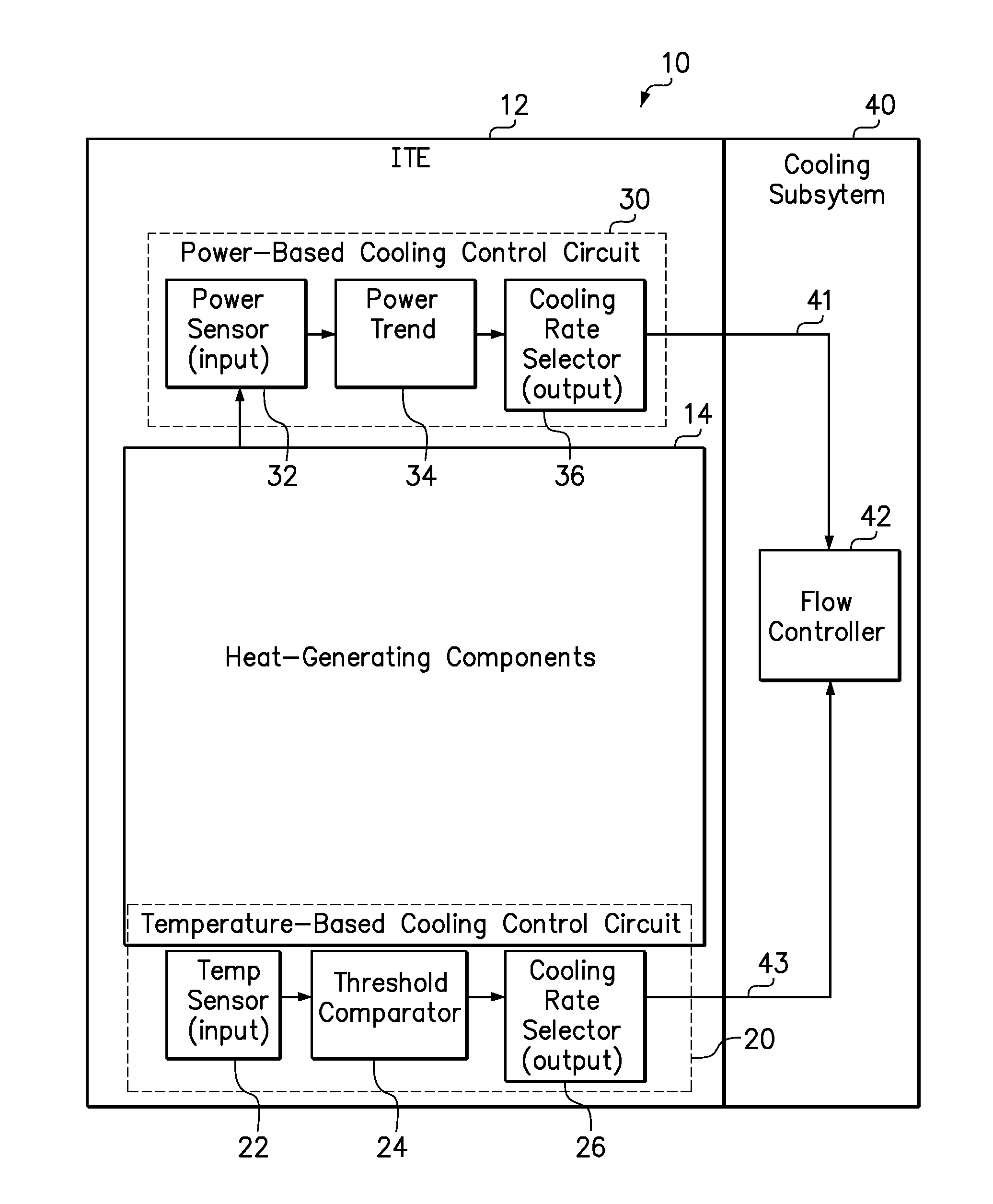
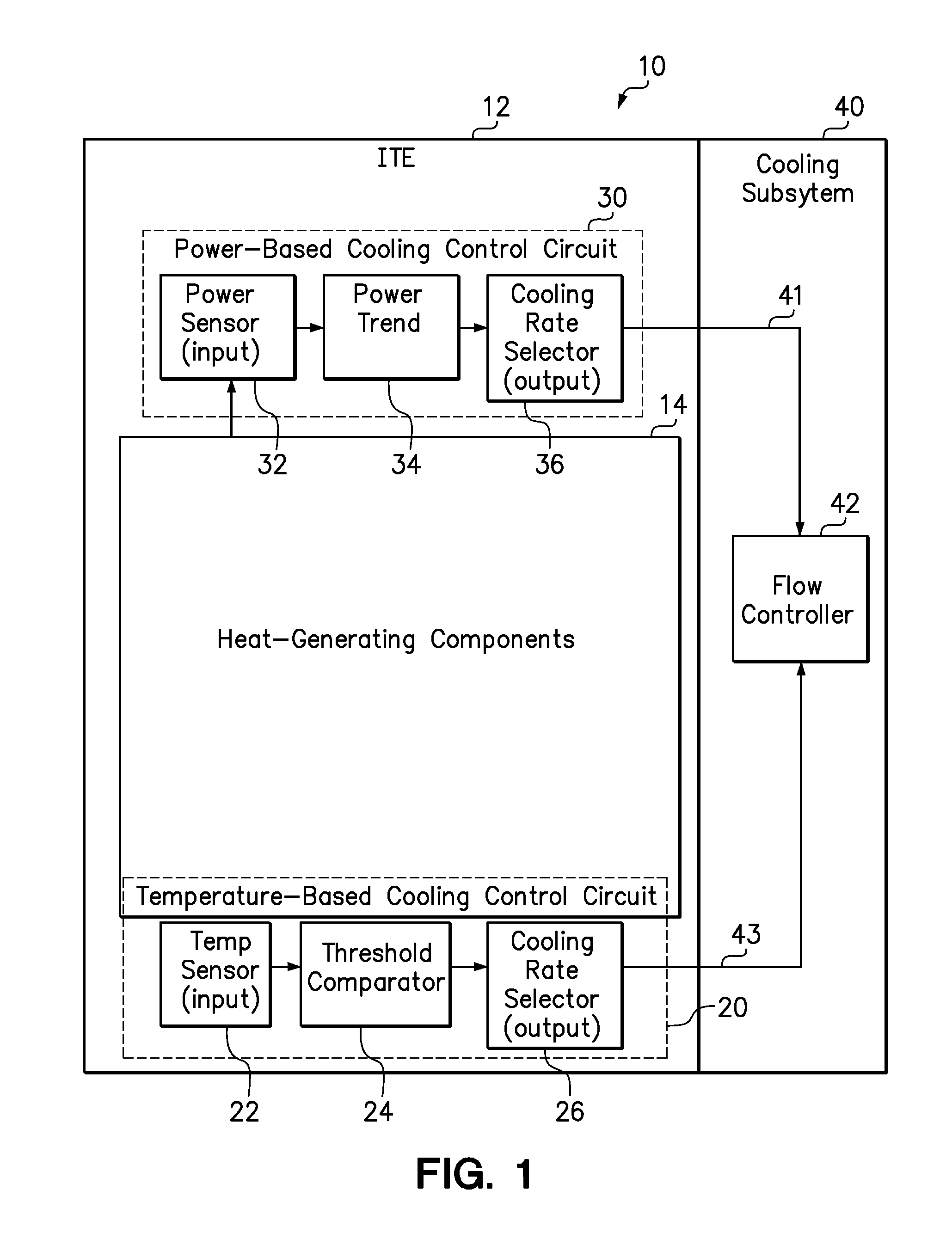
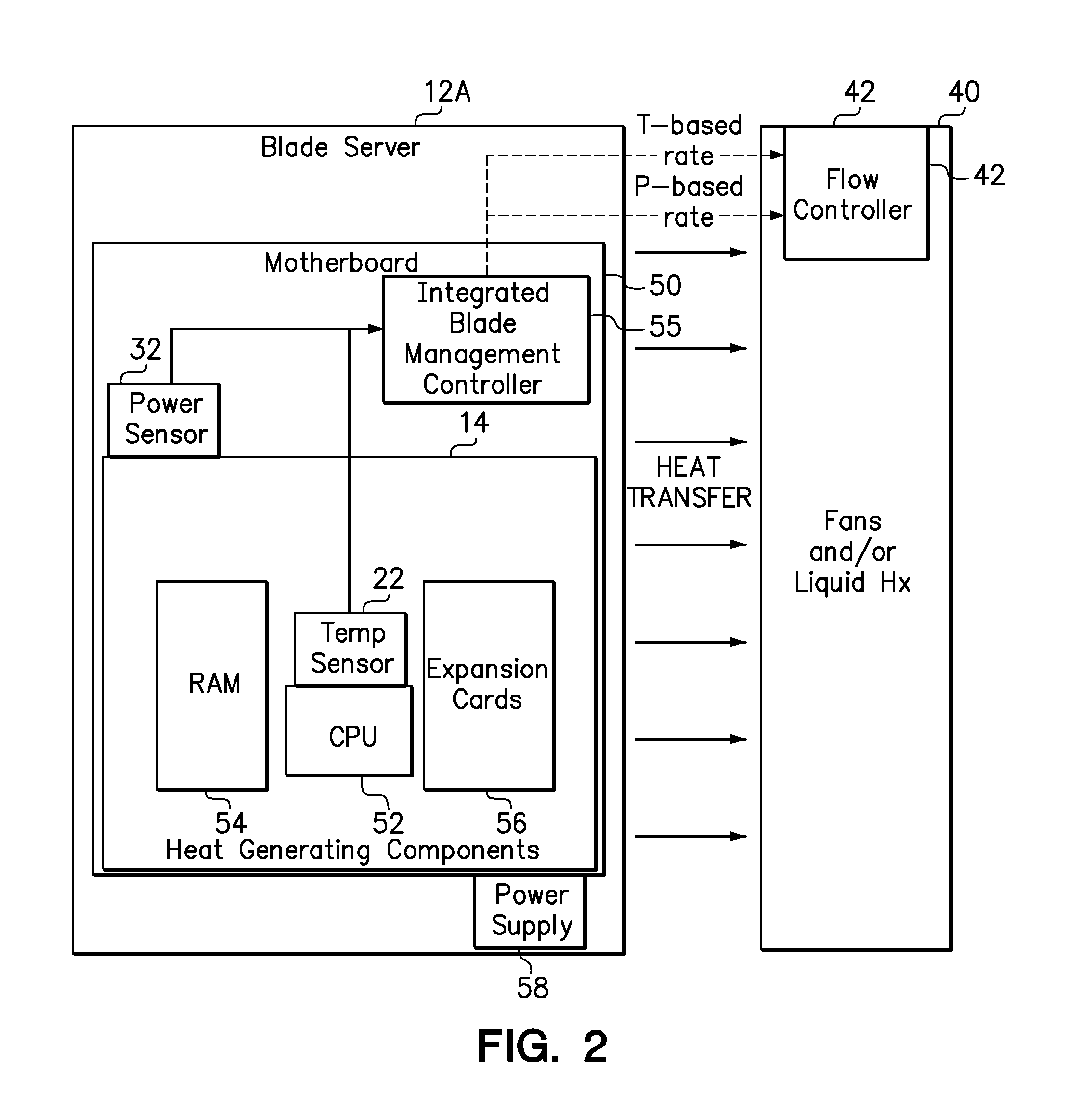
This patent describes a system and method for cooling electronic devices in real-time based on their power consumption trend. It uses a temperature sensor to monitor the device's temperature and adjust the cooling fluid flow rate accordingly. If there is no increase in temperature, the cooling fluid flow rate is increased only if the increasing power consumption trend exceeds a certain threshold. The technical effect of this system is to improve the cooling efficiency of electronic devices and prevent overheating that could cause damage, especially in server systems where a lot of heat can be generated.

Problems solved by technology

The large amount of rack-mounted computer equipment in a datacenter may collectively consume a large quantity of power and generate a large amount of heat.
The servers commonly used in datacenters are becoming more challenging to cool, as a result of parameters such as higher component packaging densities, sharper variations in server workload, and a general demand to reduce energy consumption within cooling subsystems.
Providing more cooling than necessary will consume more energy than necessary.
Conversely, too little cooling can cause a temperature threshold to be exceeded and invoke performance-reducing power reduction measures.
Of course, maintaining components at lower operating temperatures requires the consumption of additional power.

Method used


Image

  • Proactive cooling control using power consumption trend analysis
  • Proactive cooling control using power consumption trend analysis
  • Proactive cooling control using power consumption trend analysis

Examples


Embodiment Construction

[0014]The present invention includes systems and methods for proactively increasing a cooling fluid flow rate directed to a heat-generating component in response to an increasing power consumption trend of the heat-generating component. In an example system, a power-based cooling control circuit and a temperature-based cooling control circuit share control of a cooling subsystem to control the cooling fluid flow rate. The power-based cooling control circuit monitors the real-time, instantaneous power consumption of one or more of its heat-generating components, identifies and quantifies an increasing power consumption trend over a moving target time interval of a finite but non-zero duration, and selectively adjusts the cooling fluid flow rate in response to the computed power consumption trend exceeding a power threshold. In one embodiment, the target time interval may have a fixed length within the range of between 5 and 30 seconds. The target time interval is of sufficient length...


PUM


Abstract

A fluid-cooled computer system includes a plurality of heat-generating components and a cooling system configured for supplying a cooling fluid at a controlled cooling fluid flow rate to cool the heat-generating components. A temperature-based cooling control circuit includes a temperature sensor configured for sensing a temperature of the heat-generating components and control logic for increasing a cooling fluid flow rate in response to the temperature exceeding a temperature threshold. A power-based cooling control circuit is configured for identifying and quantifying an increasing power consumption trend over a target time interval and, during a period that the temperature of the electronic device does not exceed the temperature threshold, increasing a cooling fluid flow rate to the electronic device in response to the magnitude of the increasing power consumption trend exceeding a power threshold. In one option, the fluid-cooled computer system is a server and the heat-generating components include a processor.

Description

BACKGROUND[0001]1. Field of the Invention[0002]The present invention relates generally to power management and cooling in computer equipment.[0003]2. Background of the Related Art[0004]A data center is a facility where computer equipment and related infrastructure are consolidated for centralized operation and management. Computer equipment may be interconnected in a datacenter to produce large, powerful computer systems that are capable of meeting the computing requirements of entities that store and process large amounts of data, such as corporations, web hosting services, and Internet search engines. A data center may house any number of racks, with each rack capable of holding numerous modules of computer equipment. The computer equipment typically includes a large number of rack-mounted servers along with supporting equipment, such as switches, power supplies, network communications interfaces, environmental controls, and security devices. These devices are typically mounted in...

Claims


Application Information

Patent Timeline
IPC IPC(8): G05D23/19G05D7/06
CPCG05D23/19G05B13/02G05D7/0617Y02B60/1275G06F1/206G06F2200/201H05K7/20836G05D23/1917Y02D10/00
Inventor BREY, THOMAS M.KAMATH, VINODMATTESON, JASON A.
Owner LENOVO GLOBAL TECH INT LTD
Learn More