
Expandable radiopaque marker for transcatheter aortic valve implantation

a radiopaque marker and transcatheter technology, applied in the field of prosthetic heart valve replacement, can solve the problems of inability to cover, or at best difficult, and the axial and rotational orientation of the valve is difficult to determine the patient's aortic annulus relative to the patient, and the conventional delivery device, system and method suffer from some shortcomings

Inactive Publication Date: 2013-03-21
ST JUDE MEDICAL LLC
View PDF7 Cites 10 Cited by
  • Summary
  • Abstract
  • Description
  • Claims
  • Application Information

AI Technical Summary

Benefits of technology

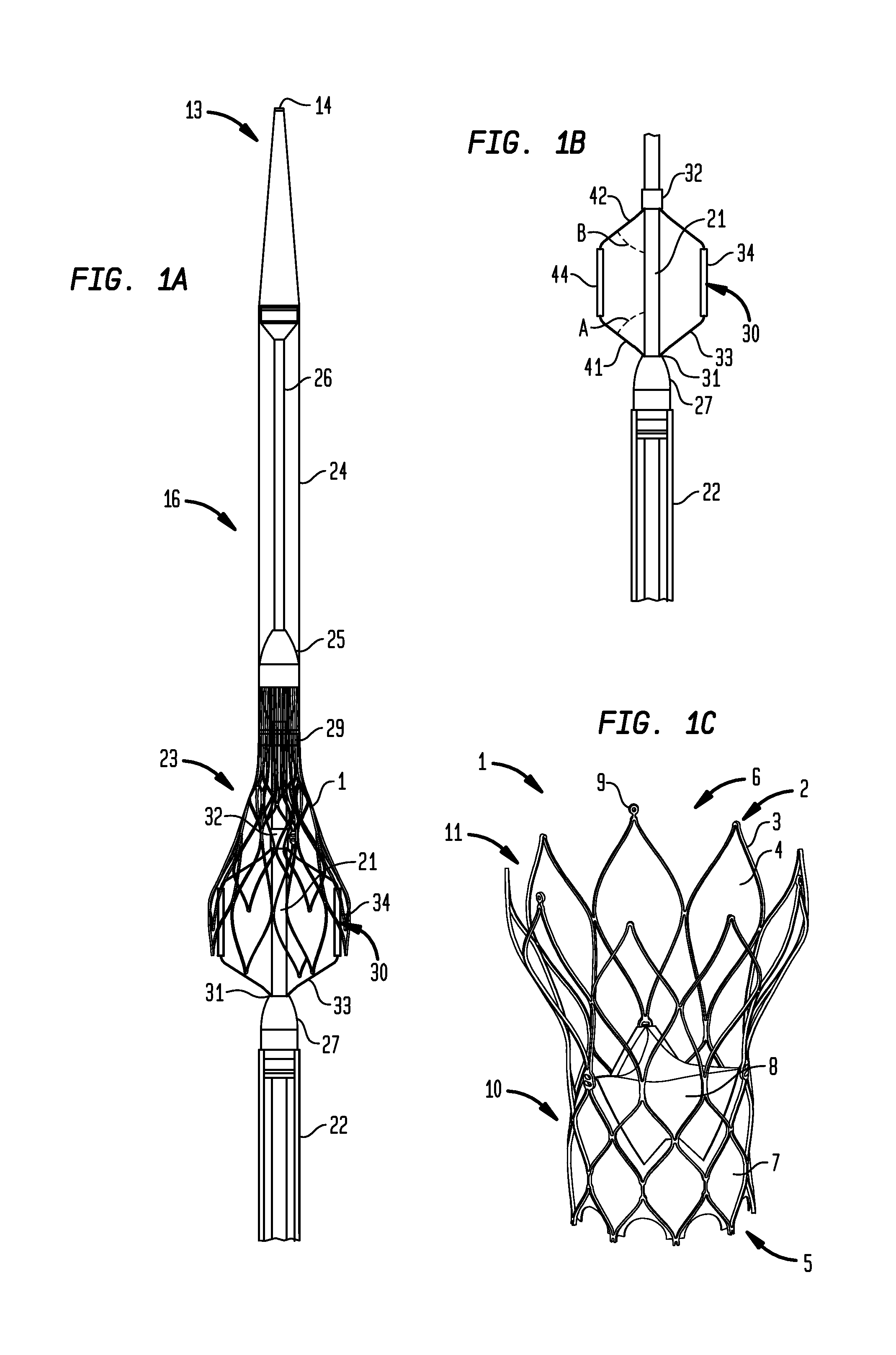
This patent describes a delivery device for a collapsible prosthetic heart valve, a marker cage for use in deployment of the valve, and a method for determining the position of the valve in a patient. The delivery device includes a support shaft, a distal sheath, and a marker cage with at least one radiopaque marker. The marker cage can be expanded to cover the valve and can be used to determine the position of the valve during deployment. The marker cage can be fixed to the support shaft or can be slid into position. The delivery device can be inserted into the patient and positioned so that the valve is at the target location. The marker cage helps to ensure accurate placement of the valve.

Problems solved by technology

Once a self-expanding valve has been fully deployed, it expands to a diameter larger than that of the sheath that previously contained the valve in the collapsed condition, making resheathing impossible, or difficult at best.
Despite the various improvements that have been made to the collapsible prosthetic heart valve delivery process, conventional delivery devices, systems, and methods suffer from some shortcomings.
For example, in conventional delivery devices for self-expanding valves, it may be difficult to determine the axial and rotational orientation of the valve relative to the patient's aortic annulus.
Some conventional delivery systems include radiopaque markers permanently attached to the valve stent, but such markers may be expensive and may become detached from the implant during or after implantation, which may cause a risk of embolism.

Method used


Image

  • Expandable radiopaque marker for transcatheter aortic valve implantation
  • Expandable radiopaque marker for transcatheter aortic valve implantation
  • Expandable radiopaque marker for transcatheter aortic valve implantation

Examples


Embodiment Construction

[0033]As used herein, the terms “proximal” and “distal” are to be taken as relative to a user (e.g., a surgeon or an interventional cardiologist) of the disclosed delivery devices. “Proximal” is to be understood as relatively close to the user and “distal” is to be understood as relatively farther away from the user.

[0034]Referring first to FIG. 1C, a collapsible prosthetic heart valve 1 includes a stent portion 2 comprising stent members 3 having a plurality of spaces 4 therebetween. The stent portion 2 includes an annulus portion 10 proximate one end 5 thereof, and an outwardly flaring aortic portion 11 proximate the other end 6 thereof. A tissue cuff 7 extends about the inner circumference of the annulus portion 10, and three leaflets 8 extend inwardly from the tissue cuff 7, with their free edges in coapting relationship. The end 6 of the stent portion 2 has a plurality of retention members 9 extending from junctions of adjacent stent members 3 and adapted to engage with accepta...


PUM


Abstract

A delivery device for a collapsible prosthetic heart valve includes a support shaft around which a compartment for the valve is defined, a distal sheath adapted to selectively cover and uncover the compartment and the valve, and a marker cage having a collapsed condition when the distal sheath covers the compartment and an expanded condition when the compartment is uncovered. The marker cage includes at least one rib having a radiopaque marker for determining the positioning of the valve as it is deployed. The valve may be assembled around the marker cage so that the marker cage does not interfere with the radial expansion of the valve during deployment.

Description

CROSS-REFERENCE TO RELATED APPLICATION[0001]The present application claims the benefit of U.S. Provisional Patent Application Ser. No. 61 / 512,490, filed Jul. 28, 2011, entitled “Expandable Radiopaque Marker for Transcatheter Aortic Valve Implantation,” the disclosure of which is hereby incorporated herein by reference.BACKGROUND OF THE INVENTION[0002]The present invention is related to prosthetic heart valve replacement, and more particularly to devices, systems, and methods for transcatheter delivery of collapsible prosthetic heart valves.[0003]Prosthetic heart valves that are collapsible to a relatively small circumferential size can be delivered into a patient less invasively than valves that are not collapsible. For example, a collapsible valve may be delivered into a patient via a tube-like delivery apparatus such as a catheter, a trocar, a laparoscopic instrument, or the like. This collapsibility can avoid the need for a more invasive procedure such as full open-chest, open-he...

Claims


Application Information

Patent Timeline
Patent Type & Authority Applications(United States)
IPC IPC(8): A61F2/24
CPCA61F2/2436A61F2250/0098A61F2/243A61F2210/0014A61F2/06A61F2/2427A61F2/246
Inventor WANG, HUISUN
Owner ST JUDE MEDICAL LLC
Learn More