
System and Method of Rendering Stereoscopic Images

a stereoscopic image and system technology, applied in the field of systems and methods of rendering stereoscopic images, can solve the problems of fatigue and discomfort, difficulty in merging binocular images,

Active Publication Date: 2013-03-21
HIMAX TECH LTD
View PDF6 Cites 23 Cited by
  • Summary
  • Abstract
  • Description
  • Claims
  • Application Information

AI Technical Summary

Benefits of technology

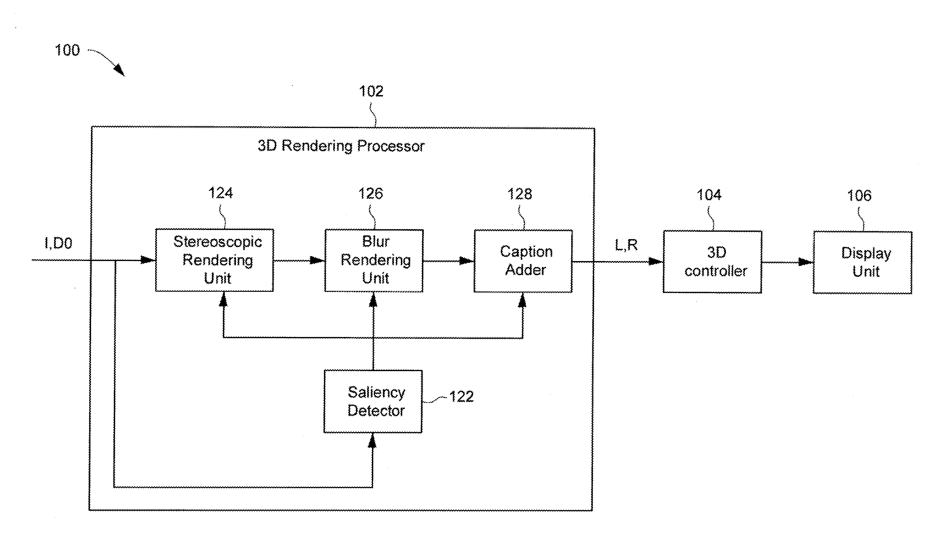
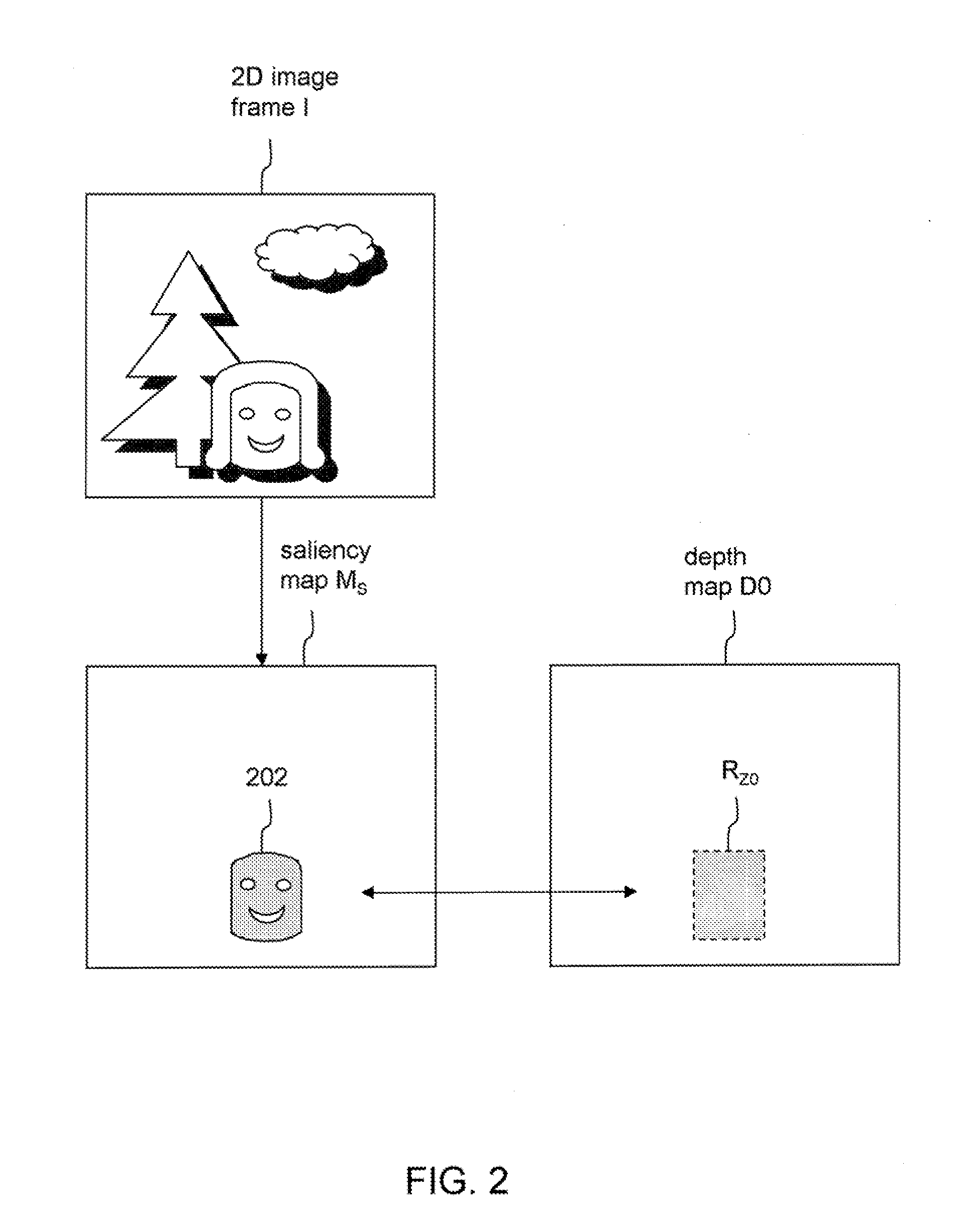
The present patent describes a system and method for creating stereoscopic images using a two-dimensional image and a depth map. The system generates a saliency map of the image and identifies the object of focus, then modifies the depth map to make the range of depth values associated with the object of focus match the depth level of the display screen. This results in a virtual stereoscopic image. The technical effect is that the system can create immersive stereoscopic images quickly and easily using existing technology.

Problems solved by technology

This results in decoupling of eye accommodation and vergence, which can cause difficulty in merging binocular images, and fatigue and discomfort.

Method used


Image

  • System and Method of Rendering Stereoscopic Images
  • System and Method of Rendering Stereoscopic Images
  • System and Method of Rendering Stereoscopic Images

Examples


first embodiment

[0026]FIG. 3 is a schematic diagram illustrating a first embodiment for modifying the depth map D0 to redistribute the depth of the identified object of focus 202. The representation of FIG. 3 is taken in a plane perpendicular to the plane of a display screen 140 of the display unit 106. The depth dimension can be exemplary represented along a horizontal axis Z perpendicular to the plane of the display screen 140. In one embodiment, the depth map D0 can be converted into an adjusted depth map D1 by offsetting / shifting the range of depth values RZ0 associated with the object of focus 202 toward a depth level ZS of the display screen 140. Suppose that Zi′ is a depth value in the adjusted range of depth values RZ1 in the depth map D1, and Zi is a depth value in the range of depth values RZ0 in the depth map D0, the relationship between Zi′ and Zi can be according to the following formulae:

Zi′=Zi+C1  (1),

[0027]wherein the constant value C1 defines the offset of the range of depth values...

second embodiment

[0030]FIG. 4 is a schematic diagram illustrating a second embodiment for modifying the depth map D0 to redistribute the depth values associated with the identified object of focus 202. The depth map D0 can be converted into a depth map D2 by compressing all of the depth values contained in the depth map D0 toward the depth level ZS of the display screen 140. For example, suppose that the range of depth values RZ0 in the initial depth map D0 is approximately centered about the depth level ZS of the display screen 140. The adjusted depth map D2 may be obtained by applying a compression operator on the initial depth map D0 such that the range of depth values RZ0 can be shrunk into the range of depth values RZ1 substantially centered about the display screen 140. In one embodiment, suppose that Zi′ is a depth value in the range of depth values RZ2 in the depth map D2, and Zi is a depth value in the range of depth values RZ0 of the depth map D0, the relationship between Zi′ and Zi can be...


PUM


Abstract

In some embodiments, a method of rendering a stereoscopic image based on a two-dimensional image frame and a depth map comprises generating a saliency map of the two-dimensional image frame, determining a region where is located an object of focus from the saliency map, modifying the depth map such that a range of depth values in the depth map that is associated the object of focus is redistributed toward a depth level of a display screen, and generating a virtual stereoscopic image frame based on the modified depth map and the two-dimensional image frame. In other embodiments, systems of rendering stereoscopic images are also described.

Description

BACKGROUND[0001]1. Field of the Invention[0002]The present invention relates to systems and methods of rendering stereoscopic images, and more particularly to stereoscopic rendering systems and methods that can reduce discomfort caused by decoupling between eye accommodation and vergence.[0003]2. Description of the Related Art[0004]For increased realism, three-dimensional (3D) stereoscopic image technology is increasingly applied in various fields such as broadcasting, gaming, animation, virtual reality, etc. To create depth perception, two image frames are typically captured or generated to simulate the left eye view and right eye view. These two image frames can be respectively provided to the left and right eyes on a two-dimensional screen so that each of the left and right eyes can only see the image associated therewith. The brain can then recombine these two different images to produce the depth perception.[0005]One known technique for rendering stereoscopic image frames inclu...

Claims


Application Information

Patent Timeline
IPC IPC(8): G06T15/00
CPCH04N13/0022H04N1/007H04N13/007H04N13/128H04N13/183
Inventor WANG, TZUNG-REN
Owner HIMAX TECH LTD
Learn More