
Ocean wave energy converter and method of mooring thereof

a technology of ocean wave energy and converter, which is applied in the direction of electric generator control, renewable energy generation, greenhouse gas reduction, etc., can solve the problems of difficult and dangerous method, difficult to adjust coil properties due to their, and high cost, so as to increase the polarity switch rate affecting coils, the effect of reducing the polarity switch rate and facilitating the incorporation of shields

Active Publication Date: 2013-03-21
AMES P FOERD
View PDF5 Cites 7 Cited by
  • Summary
  • Abstract
  • Description
  • Claims
  • Application Information

AI Technical Summary

Benefits of technology

The present invention provides an improved generator that includes counter-rotating magnet rings that efficiently correlate to ratio between upstroke buoyancy force and downstroke gravity force. The coils are fixed, eliminating brushes and easier incorporation of shields and / or weather-proof housing. The coils can be taken out of circuit for adjusting the load on the buoy. The counter-rotating magnet rotors add velocities together to increase polarity switch rate affecting coils. The mooring system includes a plurality of mooring lines conjoined to terminals, at various intervals of lower depth, resulting in fewer anchor points than if lines were not conjoined.

Problems solved by technology

The '073 patent, in particular, includes a generator that rotates with magnets and coils, but problems with the arrangement include (1) a requirement for commutation brushes that become worn or compromised in the marine environment and (2) difficulty in adjusting coil properties due to their motion.
However, traditional mooring methods involve setting multiple lines or fixed columns to the sea floor.
This method is very costly, difficult and dangerous as it involves expensive equipment and possibly diving to depths of the ocean with all the known hazards thereof.

Method used


Image

  • Ocean wave energy converter and method of mooring thereof
  • Ocean wave energy converter and method of mooring thereof
  • Ocean wave energy converter and method of mooring thereof

Examples


Embodiment Construction

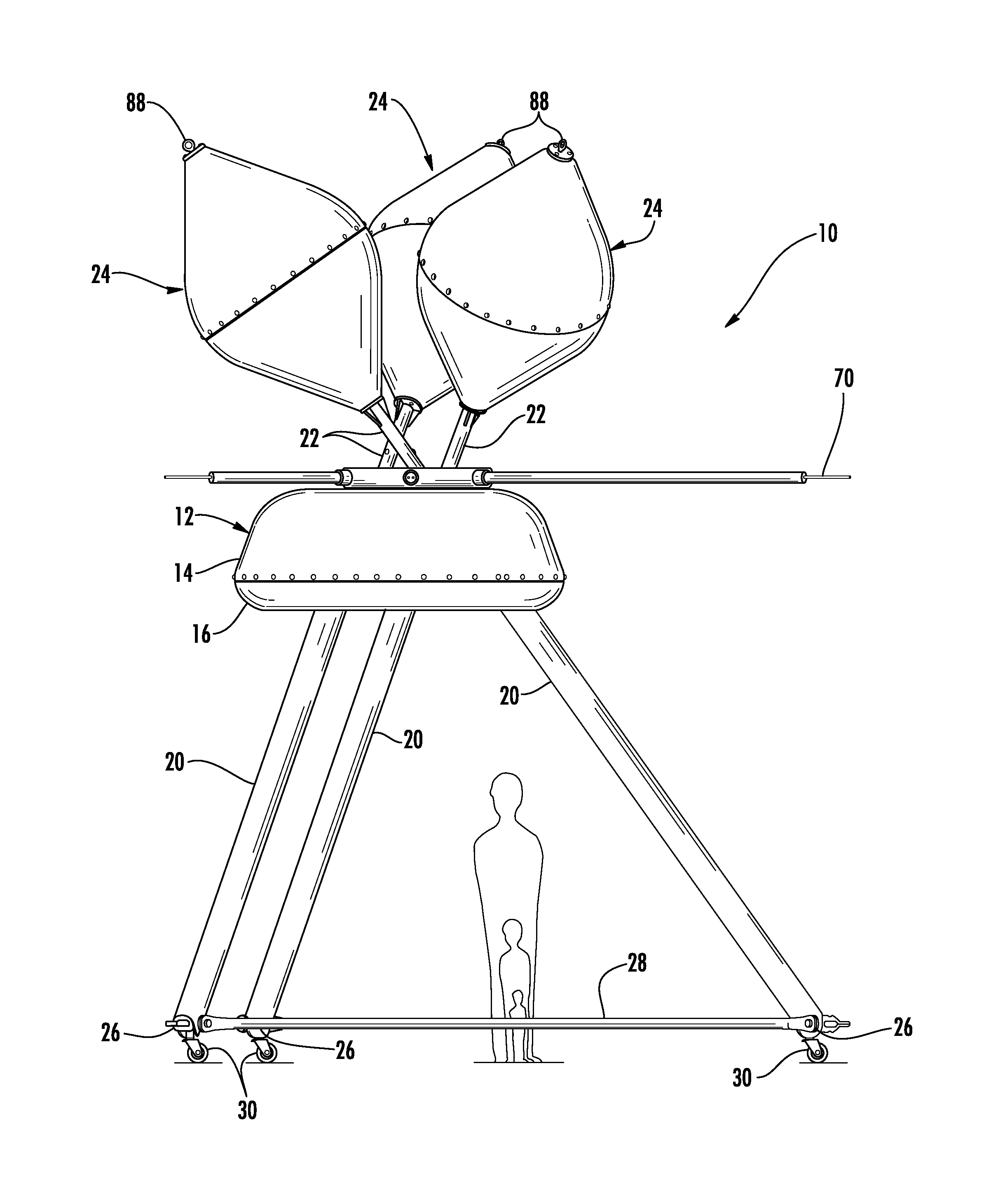
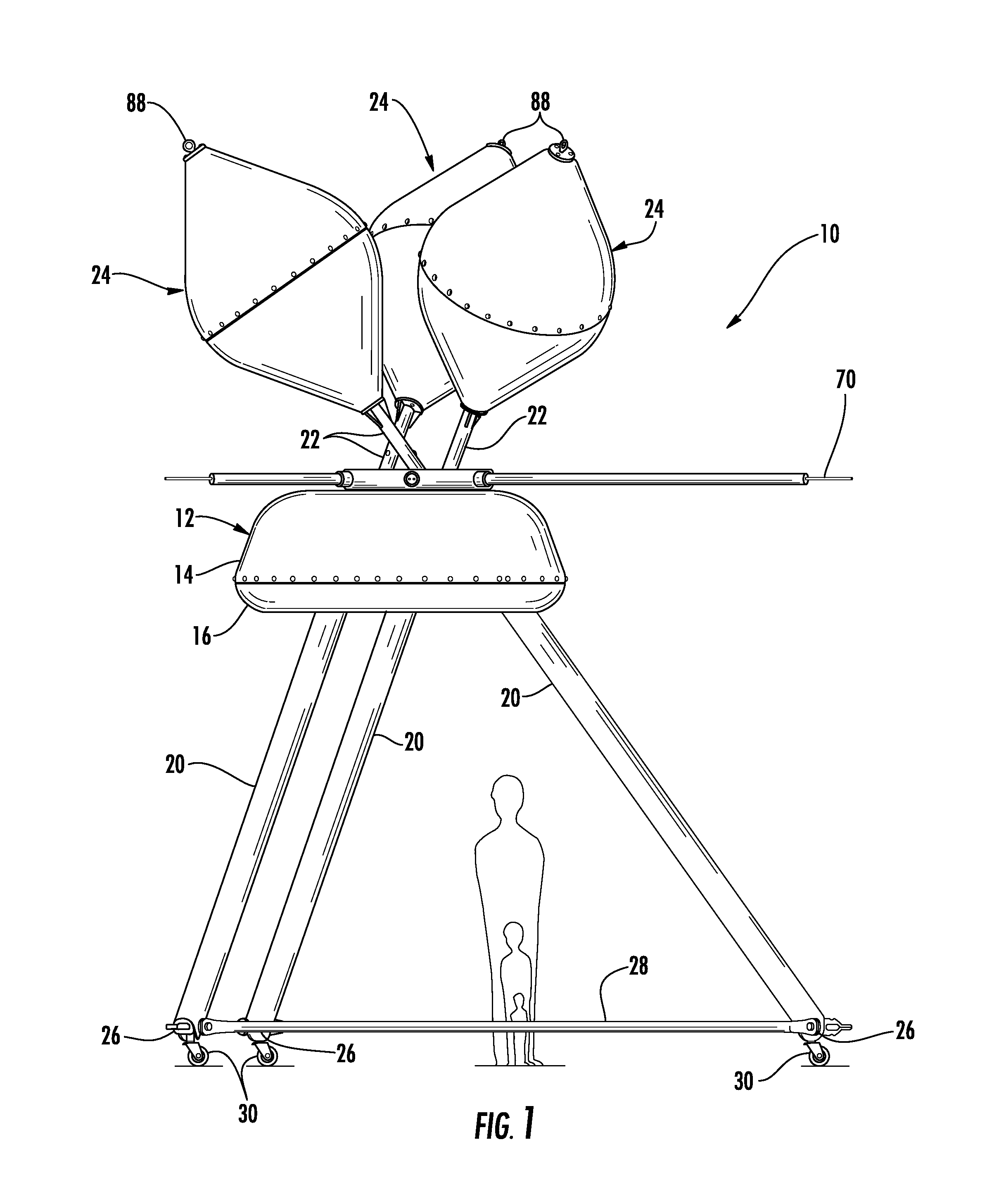
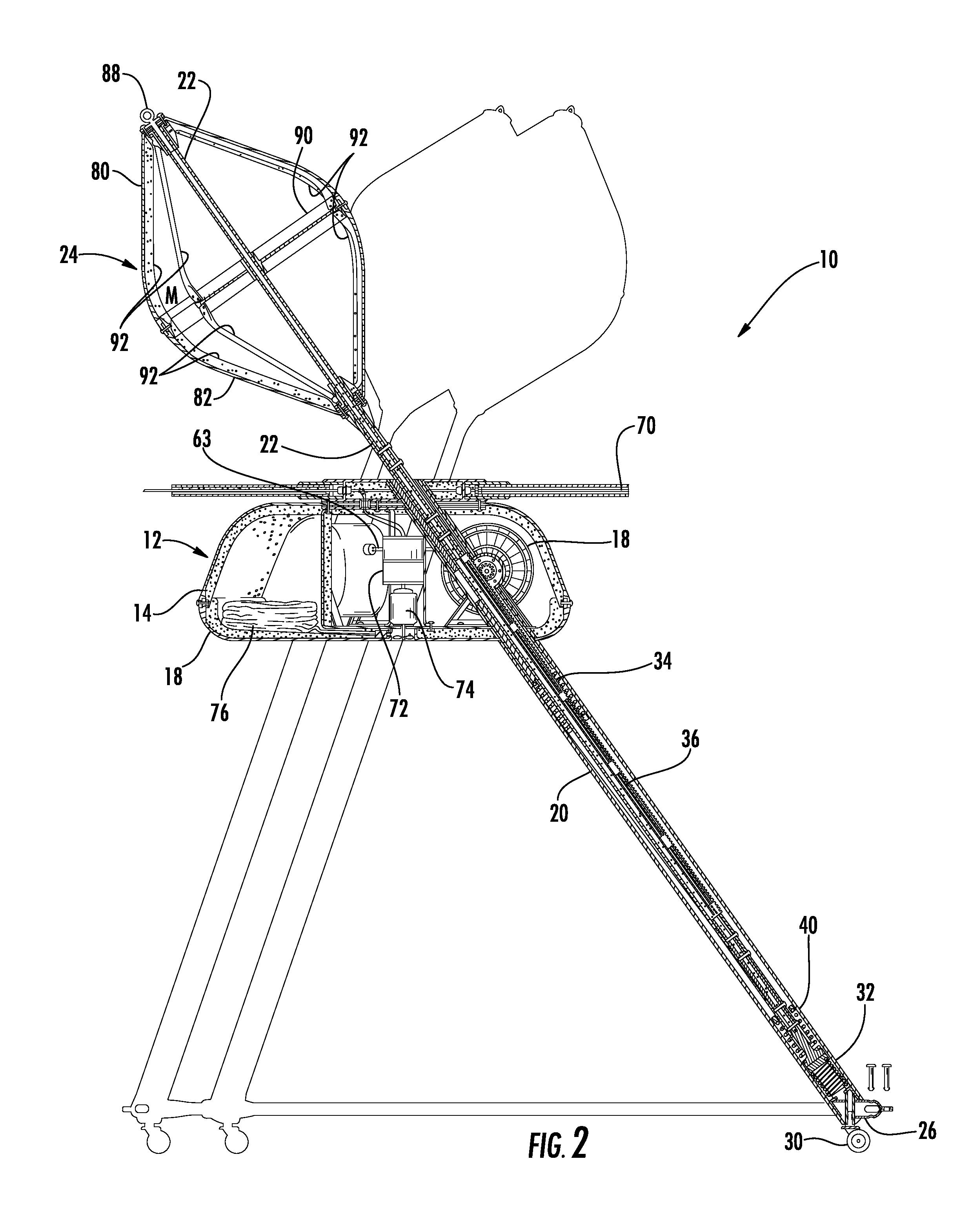
[0018]Referring to FIGS. 1 and 2, the ocean wave energy converter assembly of the present invention is shown generally at 10. As will be more fully described below, the assembly of the present invention includes three tubular framing members 20 positioned in a tetrahedral arrangement that has a main body member 12 connected at the apex of the tetrahedron. Each of the tubular framing members 20 contains a drive rod 22 slidably received therein. Each drive rod 22 is respectively connected to its own buoy 249. The assembly 10 of the present invention can be scaled appropriately to an optimal size for the known conditions or factors at the desired deployment site, such as average wave height, historical maximum wave height, depth of water, strength of currents, etc. One skilled in the art would appreciate how to select the parts and materials to construct an assembly of the present invention of the desired size.

[0019]The main body member 12 of the assembly 10 includes a top shell 14 and...


PUM


Abstract

An apparatus for converting the kinetic energy of ocean waves into electricity is disclosed. The apparatus includes a main body member. A generator is located within the main body member. The generator includes a axle having a positive direction and a negative direction. An inner rotor is driven by the axle, wherein the inner rotor is driven only in the negative direction of the axle. An outer rotor surrounds the inner rotor and is also being driven by the axle, wherein the outer rotor is driven only in the positive direction of the driveshaft. A stationary ring is located between the inner rotor and the outer rotor. A drive rod, having a buoy attached to one end, is configured to freely move between an upstroke position and a downstroke position. The drive rod drives the generator as it reciprocates between the upstroke position and the downstroke position.

Description

CROSS-REFERENCE TO RELATED APPLICATION[0001]This patent document claims priority to earlier filed U.S. Provisional Patent Application Ser. No. 61 / 536,642, filed on Sep. 20, 2011, the entire contents of which are incorporated herein by reference.BACKGROUND[0002]1. Technical Field[0003]The present patent document relates generally to an apparatus for converting the energy of wave motion on the surface of a body of water to electricity.[0004]2. Background of the Related Art[0005]Generating electricity via ocean waves is a renewable energy source that has yet to be fully realized. Because ocean wave energy represents an unlimited, clean, renewable energy source, harnessing it is highly desirable to power our modern society.[0006]Prior ocean wave energy converters, such as Ames, U.S. Pat. Nos. 4,232,230; 4,672,222; and 7,352,073 (incorporated herein by reference), although revolutionary in concept and design, suffer from several limitations. The '073 patent, in particular, includes a gen...

Claims


Application Information

Patent Timeline
Patent Type & Authority Applications(United States)
IPC IPC(8): F03B13/18
CPCF03B13/18Y02E10/38Y02E10/223F03B3/00Y02E10/20Y02E10/30
Inventor AMES, P. FOERD
Owner AMES P FOERD
Learn More