
Thermal treatment apparatus, temperature control system, thermal treatment method, temperature control method, and non-transitory computer readable medium embodied with program for executing the thermal treatment method or the temperature control method

a technology of thermal treatment and computer readable medium, which is applied in the direction of lighting and heating apparatus, furniture, charge manipulation, etc., can solve the problems of increasing power consumption during the cooling process, and achieve the effect of preventing the generation of a difference in cooling speed and increasing power consumption

Inactive Publication Date: 2013-03-14
TOKYO ELECTRON LTD
View PDF6 Cites 307 Cited by
  • Summary
  • Abstract
  • Description
  • Claims
  • Application Information

AI Technical Summary

Benefits of technology

The present invention provides a thermal treatment apparatus, method, and control system to prevent uneven cooling of a container without increasing power consumption. The method includes heating the container and cooling it by supplying gas into the container at different locations. The flow rates of the gases are independently controlled to equalize the cooling speed in the container. This results in a more uniform and efficient cooling process.

Problems solved by technology

However, since the heaters are controlled in such a way that an amount of heat generated by the heaters provided in a portion having a relatively higher cooling speed is greater than an amount of heat generated by the heaters provided in another portion, power consumption during the cooling process increases.
Also, the above-described problem is not limited to a case where the substrates are held in a vertical direction and may occur even when the substrates are held at predetermined intervals in a certain direction.
In addition, the above-described problem is not limited to a case of cooling a thermal treatment container for thermally processing the substrates and may occur even when a container extending in a certain direction is cooled.

Method used


Image

  • Thermal treatment apparatus, temperature control system, thermal treatment method, temperature control method, and non-transitory computer readable medium embodied with program for executing the thermal treatment method or the temperature control method
  • Thermal treatment apparatus, temperature control system, thermal treatment method, temperature control method, and non-transitory computer readable medium embodied with program for executing the thermal treatment method or the temperature control method
  • Thermal treatment apparatus, temperature control system, thermal treatment method, temperature control method, and non-transitory computer readable medium embodied with program for executing the thermal treatment method or the temperature control method

Examples


an embodiment

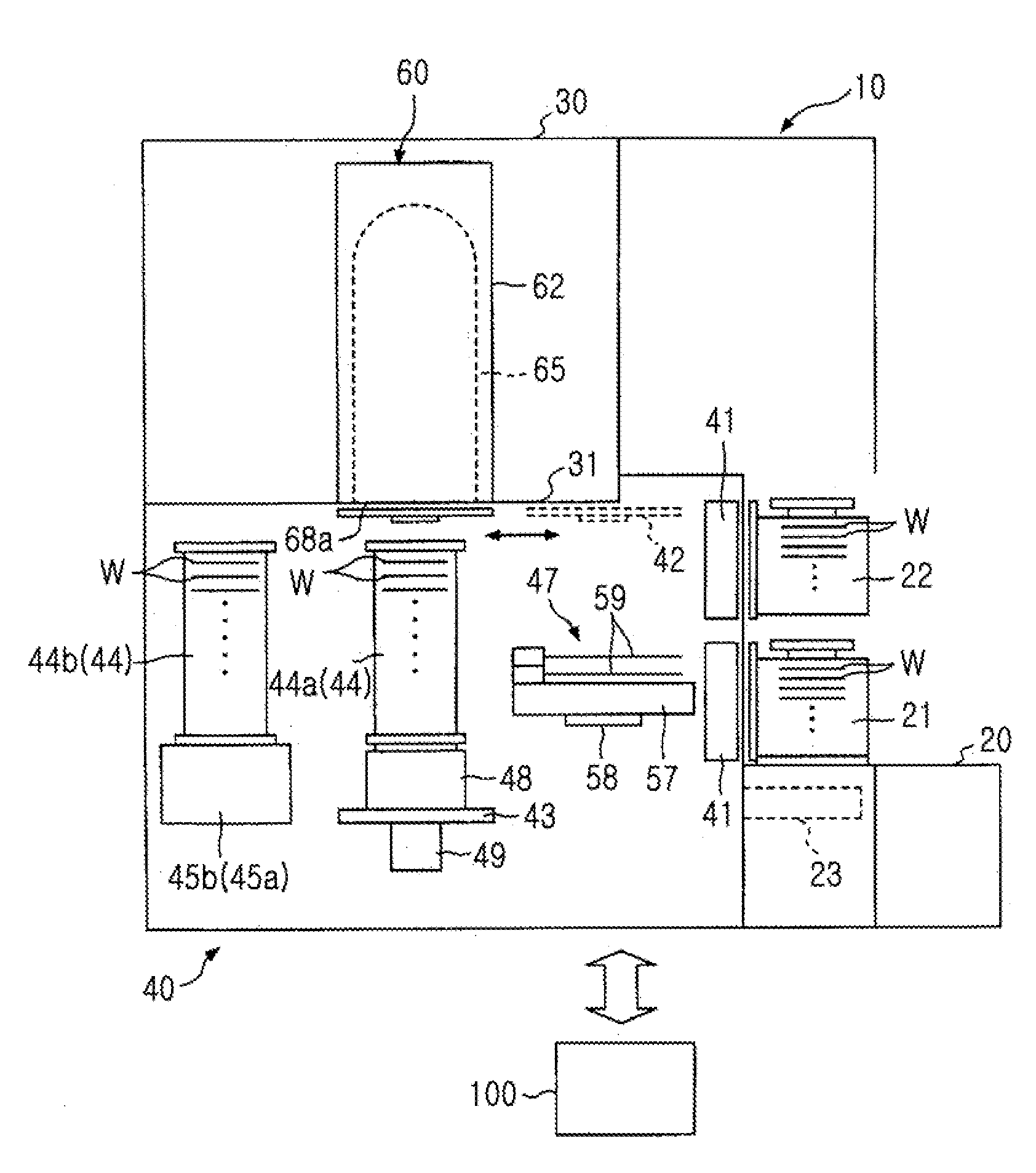
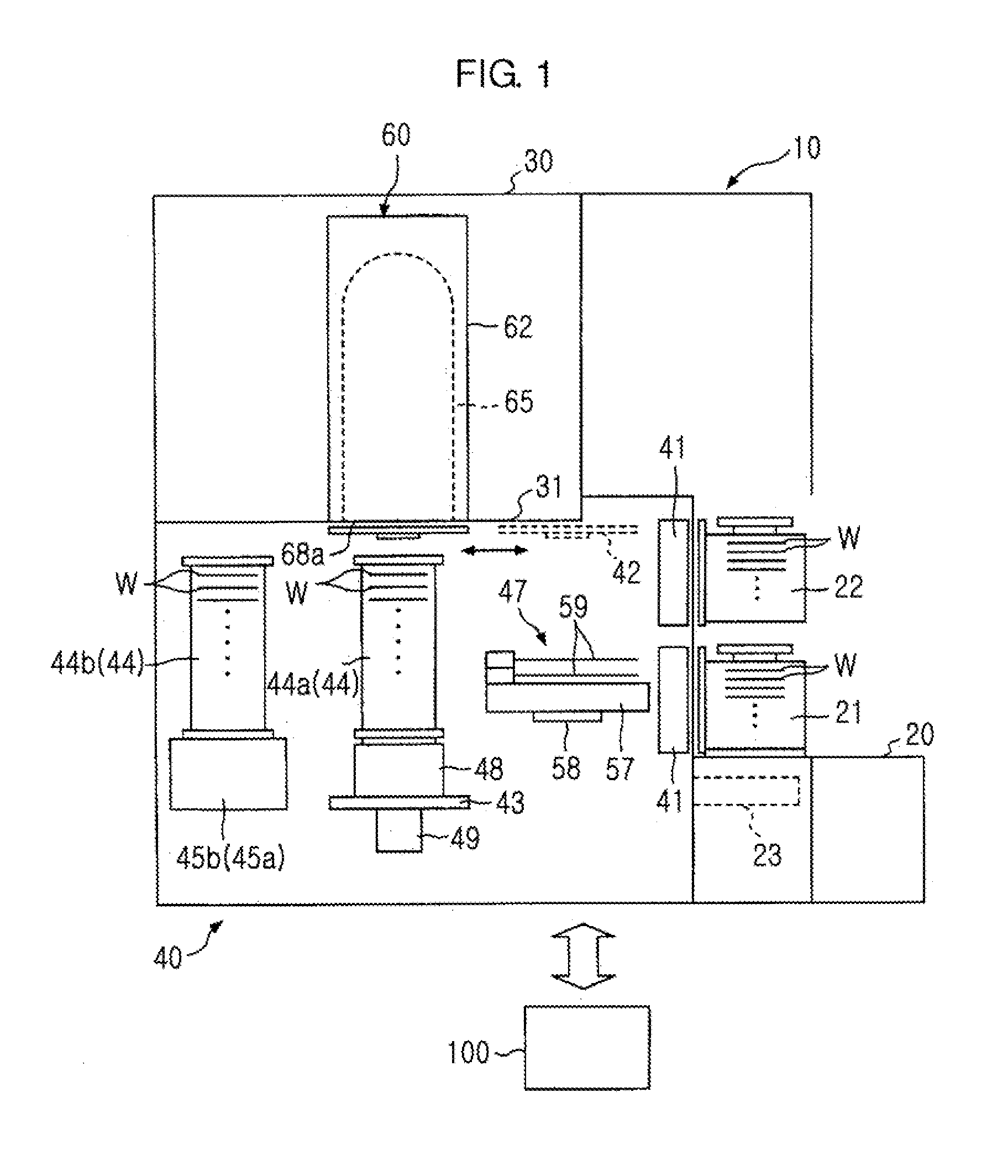
[0107]In the present embodiment, the boats 44 holding the wafers W are actually carried into the processing container 65, temperatures of each of the unit areas during step S15 (cooling process) are measured, and a difference in temperature between the unit areas is evaluated. A result of the evaluation will be described below.

[0108]As the present embodiment, when the opening degree of the valve 97-1 closest to the opening 67 is previously set to 50% and the opening degrees of the remaining valves 97-2 to 97-10 are previously set to 100%, the cooling process is performed in such a way that the temperature is decreased from 800° C. to 400° C. as an example of step S15 (cooling process). Also, as a comparative example 1, when the opening degrees of all the valves 97-1 to 97-10 are previously set to 100%, the cooling process is performed in such a way that the temperature is decreased from 800° C. to 400° C., similar to the present embodiment. Also, in the present embodiment and the co...


PUM

PropertyMeasurementUnit
Temperatureaaaaaaaaaa
Flow rateaaaaaaaaaa
Distributionaaaaaaaaaa

Abstract

A thermal treatment apparatus includes a processing container, a substrate holding unit for holding a plurality of substrates at predetermined intervals in a direction inside the processing container, a heating unit for heating the processing container, a supply unit for supplying gas, a plurality of supply ports provided respectively at different locations in the direction, and a cooling unit for cooling the processing container by supplying the gas into the processing container by the supply unit via each of the supply ports, wherein the supply unit is provided in such a way that the supply unit independently controls flow rates of the gases supplied via each of the supply ports.

Description

CROSS-REFERENCE TO RELATED PATENT APPLICATIONS[0001]This application claims the benefit of Japanese Patent Application No. 2011-199621, filed on Sep. 13, 2011 in the Japan Patent Office, the disclosure of which is incorporated herein in its entirety by reference.BACKGROUND OF THE INVENTION[0002]1. Field of the Invention[0003]The present invention relates to a thermal treatment apparatus, a temperature control system, a thermal treatment method, a temperature control method, and a non-transitory computer readable medium embodied with a program for executing the thermal treatment method or the temperature control method.[0004]2. Description of the Related Art[0005]In manufacture of a semiconductor device, various processing apparatuses are used to perform processes such as oxidation, dispersion, chemical vapor deposition (CVD), etc. on a substrate, for example, a semiconductor wafer. A vertical thermal treatment apparatus capable of simultaneously performing a thermal treatment on a p...

Claims


Application Information

Patent Timeline
IPC IPC(8): F27D15/02F27D3/00F27D21/00
CPCH01L21/67109H01L21/67248C23C16/481H01L21/67757C23C16/463H01L21/67303
Inventor YOSHII, KOJIYAMAGUCHI, TATSUYAWANG, WENLINGSAITO, TAKANORI
Owner TOKYO ELECTRON LTD
Learn More