Centrifugal Fan Assembly

Inactive Publication Date: 2013-03-14
BROSE FAHRZEUGTEILE GMBH & CO KG HALLSTADT (DE)
View PDF9 Cites 6 Cited by
  • Summary
  • Abstract
  • Description
  • Claims
  • Application Information

AI Technical Summary

Benefits of technology

The present invention provides a centrifugal fan assembly with a guiding vane device that can improve fan efficiency and reduce flow separation. The guiding vane device can gradually accelerate incoming non-rotating airflow to the rotating speed of the blower wheel, resulting in a smooth acceleration and the elimination of flow separation at the leading edge of the blow fan blades. The centrifugal fan assembly with the guiding vane device operates more efficiently, reduces noise, and provides significantly more airflow for the same size and lower operating speed. The curved leading edge of the guiding vanes also increases performance. The guiding vane device can be integrally formed with the blower wheel, reducing manufacturing costs and increasing stability.

Problems solved by technology

Furthermore, low noise generation increases the safety of the passengers in the vehicle, because low noise increases the attention of the driver.
The noise of a centrifugal fan assembly is produced mainly by the rotating parts of the centrifugal fan assembly, especially by the blower wheel.
This sudden increase of rotational speed results in a separation of the airflow at the leading edge of the fan blades of the blower wheel.
This separation result in increased noise, vibration, and harshness as well as in degrading the efficiency of the centrifugal fan.
The separation of the airflow also reduces the volume efficiency of the blower unit.
However, this centrifugal fan assembly is ineffective since the stationary device cannot create enough rotating velocity in incoming airflow.

Method used


Image

  • Centrifugal Fan Assembly
  • Centrifugal Fan Assembly
  • Centrifugal Fan Assembly

Examples


Embodiment Construction

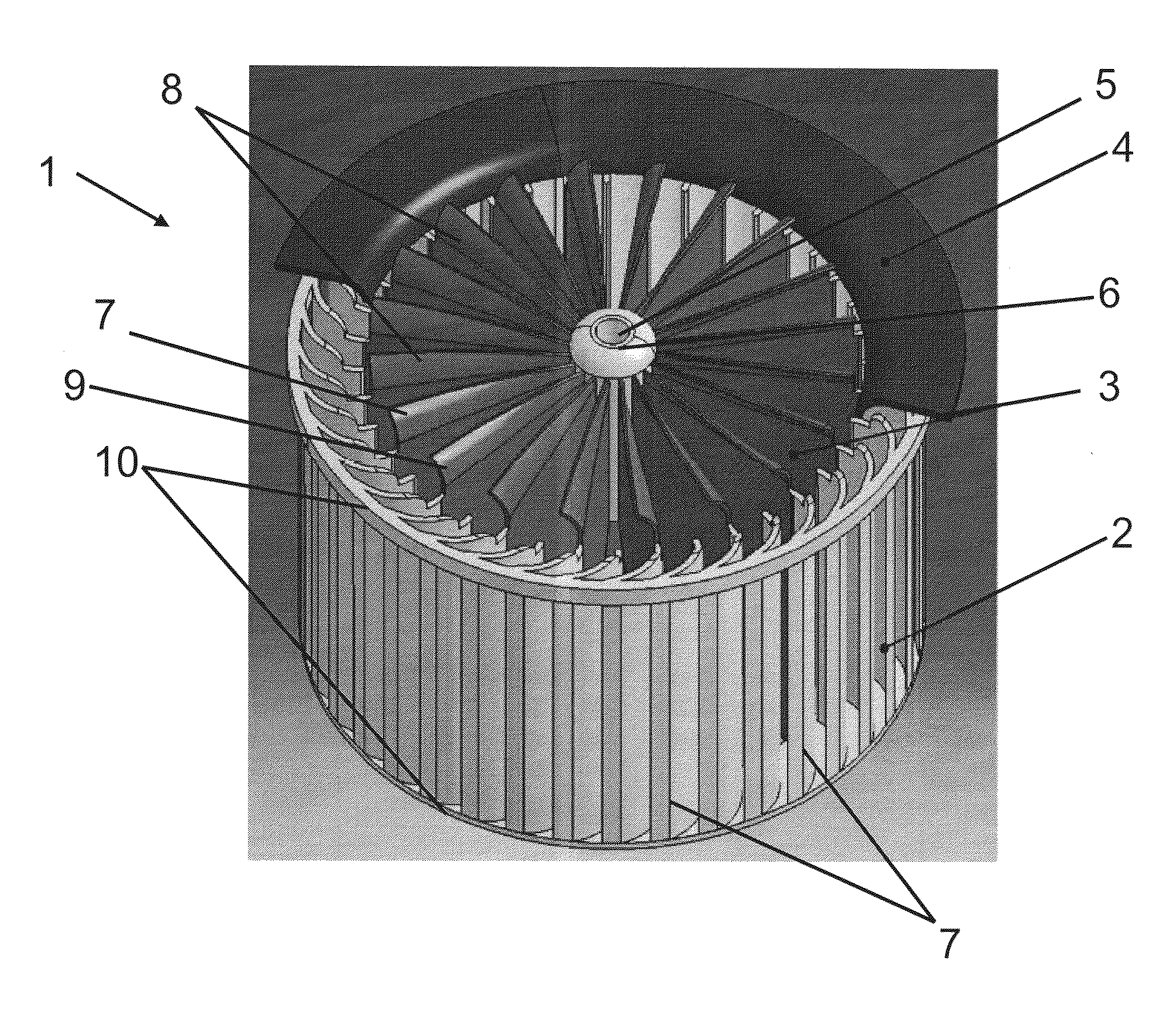
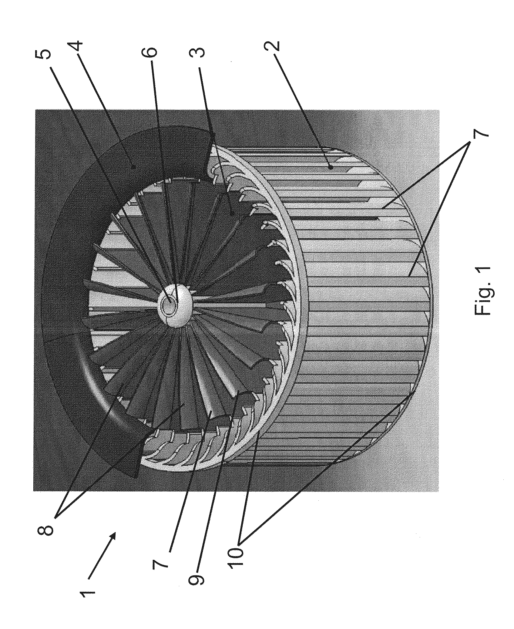
[0037]FIG. 1 is a perspective view of a centrifugal fan assembly 1 for an automotive vehicle according to the present invention. The centrifugal fan assembly 1 comprises a housing 4 and a blower wheel 2 including a first number of fan blades 7. The blower wheel 2 is rotatably mounted within the housing 4 and may be driven by an electric drive, a direct drive, a belt drive, a magnetic coupling or a hydraulic coupling (not shown).

[0038]The fan blades 7 of the blower wheel 2 are oriented axially with respect to the axis of rotation 5 of the blower wheel 2. The blower wheel fan blades 7 may be for example forward-curved fan blades, backward curved fan blades or straight radial fan blades. The fan blades 7 are constructed to generate an airflow, which flows axially into the blower wheel 2 and radially out of the blower wheel 2.

[0039]Furthermore, the centrifugal fan assembly 1 comprises a guiding vane device 3 including a second number of guiding vanes 8. The guiding vanes 8 of the guidin...


PUM


Abstract

The present invention relates to a centrifugal fan assembly and a HVAC-system, comprising a housing, a blower wheel comprising a plurality of fan blades, the blower wheel being rotatably mounted in the housing and constructed to generate an airflow flowing axially into the blower wheel and radially out from the blower wheel, a guiding vane device including a plurality of guiding vanes, the guiding vane device being coupled to the blower wheel and configured to guide the airflow into the blower wheel.

Description

FIELD OF THE INVENTION[0001]The present invention relates generally to a HVAC-System. More particularly, the present invention relates to a centrifugal fan assembly for automotive vehicles.BACKGROUND OF THE INVENTION[0002]Centrifugal fan assemblies generally include a blower wheel that is arranged in a housing and which may be driven by an electric motor. The blower wheel has curved blade fans which draw air in axially, along the axis of rotation of the blower wheels, and discharge air radially outwardly. Such fan assemblies are used in a variety of applications, such as in automotive applications.[0003]In automotive applications it is always an object to minimize the generation of noise, to make the driving of the automotive vehicle as convenient as possible. Furthermore, low noise generation increases the safety of the passengers in the vehicle, because low noise increases the attention of the driver.[0004]The noise of a centrifugal fan assembly is produced mainly by the rotating ...

Claims


Application Information

Patent Timeline
IPC IPC(8): F04D29/44
CPCF04D17/025F04D29/4226F04D29/282
Inventor HONG, TAO
Owner BROSE FAHRZEUGTEILE GMBH & CO KG HALLSTADT (DE)
Why Eureka
Try Eureka