
Terminal apparatus and response signal transmitting method

a terminal and response signal technology, applied in multiplex communication, orthogonal multiplex, wireless commuication services, etc., can solve the problems of terminal not knowing whether or not downlink data addressed to the terminal exists in the downlink component carrier, and the failure to receive downlink allocation control information on the terminal side is not always successful

Active Publication Date: 2013-03-14
PANASONIC INTELLECTUAL PROPERTY CORP OF AMERICA
View PDF19 Cites 11 Cited by
  • Summary
  • Abstract
  • Description
  • Claims
  • Application Information

AI Technical Summary

Benefits of technology

The patent invention allows for smooth communication between a base station and a terminal when the base station changes the configuration of carrier aggregation for the terminal. This ensures that the terminal can still transmit an uplink response signal to the base station even if there is a difference in recognition regarding the configuration of the number of downlink component carriers in the terminal.

Problems solved by technology

However, since each terminal makes a blind decision on downlink allocation control information addressed to the terminal apparatus in each subframe (transmission unit time), reception of downlink allocation control information is not always successful on the terminal side.
When the terminal fails to receive downlink allocation control information addressed to the terminal in a certain downlink component carrier, the terminal cannot even know whether or not downlink data addressed to the terminal exists in the downlink component carrier.

Method used


Image

  • Terminal apparatus and response signal transmitting method
  • Terminal apparatus and response signal transmitting method
  • Terminal apparatus and response signal transmitting method

Examples


Embodiment Construction

[0045]Hereinafter, an embodiment of the present invention will be described in detail with reference to the accompanying drawings. Identical components in the embodiment will be assigned identical reference numerals and overlapping descriptions thereof will be omitted.

[0046][Overview of Communication System]

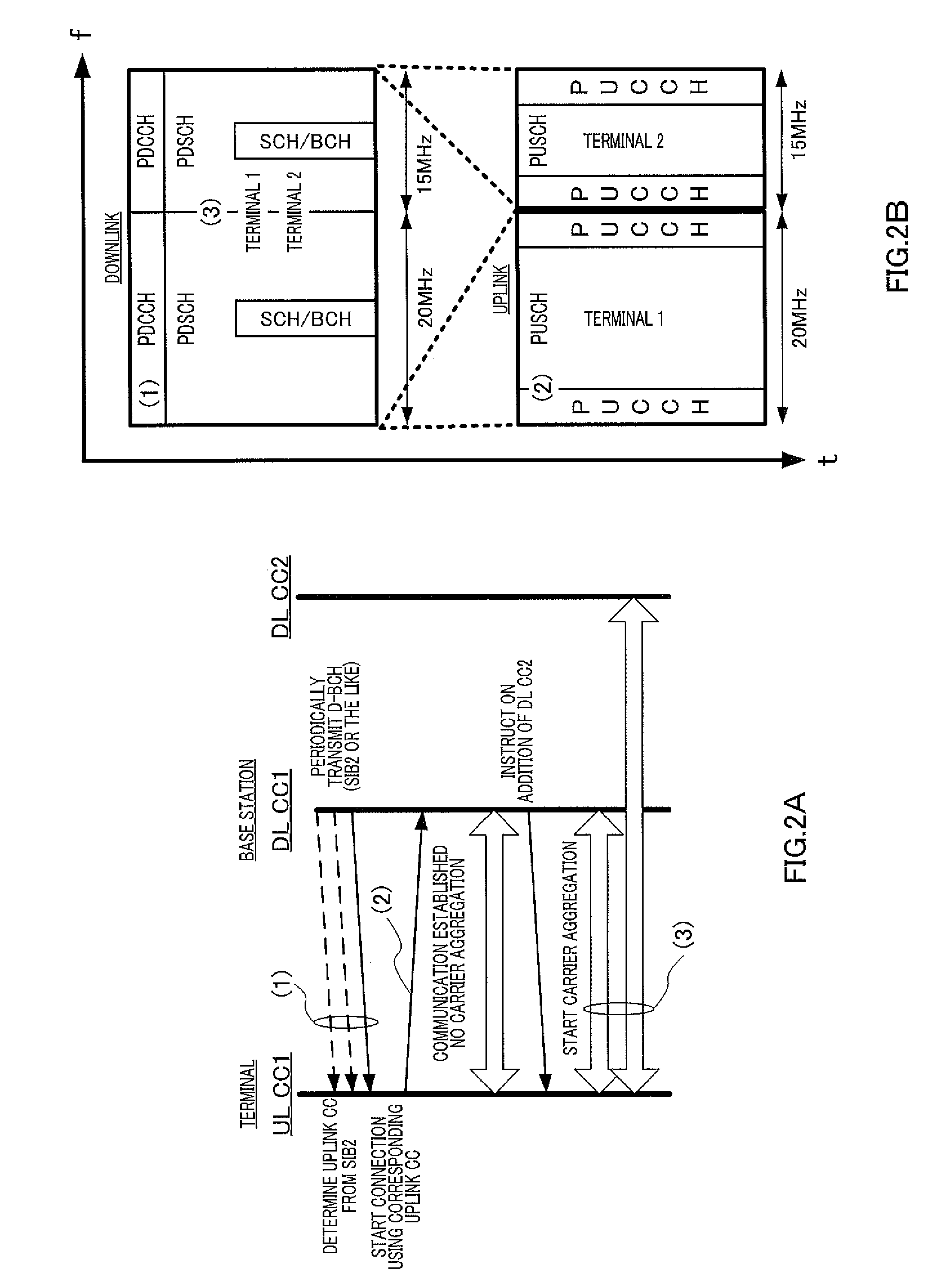
[0047]A communication system including a base station 100 (FIG. 5) and terminal 200 (FIG. 6) which will be described later performs communication using an uplink component carrier and a plurality of downlink component carriers associated with the uplink component carrier, that is, communication using asymmetric carrier aggregation specific to terminal 200. Furthermore, this communication system also includes terminals that have no capability of performing communication using carrier aggregation unlike terminal 200, and perform communication using one downlink component carrier and one uplink component carrier associated therewith (that is, communication without carrier aggregatio...


PUM


Abstract

This invention is related to a terminal apparatus that can normally transmit an upstream response signal. A response signal generating unit (212); generates response signals on the basis of a setting rule in which pattern candidates of success or failure in the reception of downstream allocation control information and downstream data are associated with the phase points of response signals and further in which the phase point of one response signal associated with an arbitrary pattern of success or failure in the reception during the second communication has been set to be identical with the phase points of two response signals associated with pattern candidates for which the pattern of success or failure in the reception at PCC during the first communication is identical with the arbitrary pattern and for which all of the receptions of downstream allocation control information have been failed at SCC.

Description

TECHNICAL FIELD[0001]The present invention relates to a terminal apparatus and a response signal transmission method.BACKGROUND ART[0002]3GPP LTE adopts OFDMA (Orthogonal Frequency Division Multiple Access) as a downlink communication scheme. In a radio communication system to which 3GPP LTE is applied, a base station apparatus (hereinafter, abbreviated as “base station”) transmits a synchronization signal (i.e., Synchronization Channel: SCH) and broadcast signal (i.e., Broadcast Channel: BCH) using predetermined communication resources. A terminal apparatus (hereinafter abbreviated as “terminal”) locates an SCH to secure synchronization with the base station first. After that, the terminal reads BCH information to acquire base station-specific parameters (e.g., frequency bandwidth) (see Non-Patent Literatures 1, 2, and 3).[0003]Upon completion of the acquisition of the base station-specific parameters, the terminal sends a connection request to the base station to thereby establish...

Claims


Application Information

Patent Timeline
IPC IPC(8): H04W72/04
CPCH04J11/0079H04J13/0048H04L5/0094H04L1/1861H04L5/001H04J13/0055H04W72/23
Inventor NAKAO, SEIGO
Owner PANASONIC INTELLECTUAL PROPERTY CORP OF AMERICA
Learn More