Image capturing lens system

a technology of image capturing and lens system, which is applied in the field of image capturing lens system, can solve the problems of reducing the degree of freedom in arranging the lens system, the inability to easily the complicated process of adhesion of glass lenses, so as to reduce the total track length of the system, improve image quality, and reduce the effect of total track length

Active Publication Date: 2013-03-14
LARGAN PRECISION
View PDF4 Cites 10 Cited by
  • Summary
  • Abstract
  • Description
  • Claims
  • Application Information

AI Technical Summary

Benefits of technology

The patent describes an image capturing lens system that has a reduced photosensitivity and better image quality. The system has a compact design with a short total track length. The first lens element provides significant refractive power and helps reduce the total track length of the system. The second lens element corrects astigmatism and the fourth lens element positions the system's principal point away from the image plane to further shorten the total track length. The first lens element can be a bi-convex or meniscus lens element, and the second lens element can have a concave image-side surface to effectively correct astigmatism and chromatic aberration. The third lens element corrects astigmatism and the fourth lens element positions the system's principal point away from the image plane to reduce astigmatism and improve sensing efficiency. The system also has an improved off-axis aberration correction.

Problems solved by technology

First, the degree of freedom in arranging the lens system is curtailed due to the employment of excessive number of spherical glass lenses; thus, the total track length of the system cannot be reduced easily.
Second, the process of adhering glass lenses together is complicated, posing difficulties in manufacturing.
Moreover, the popularity of high-class portable devices such as Smart Phone and PDA (Personal Digital Assistant) drives the rapid improvements in high resolution and image quality of the current compact imaging lens systems, conventional four lens elements systems no longer satisfy the higher level camera modules.

Method used


Image

  • Image capturing lens system
  • Image capturing lens system
  • Image capturing lens system

Examples


embodiment 1

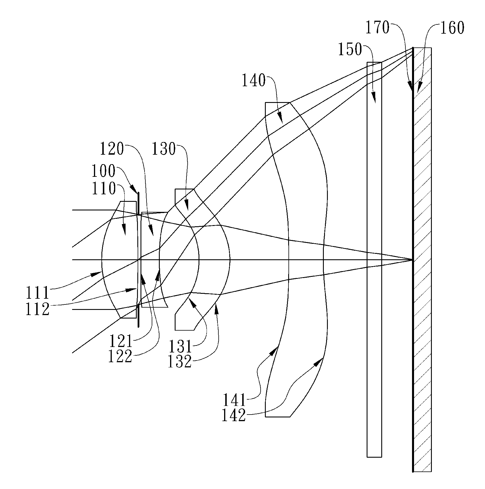
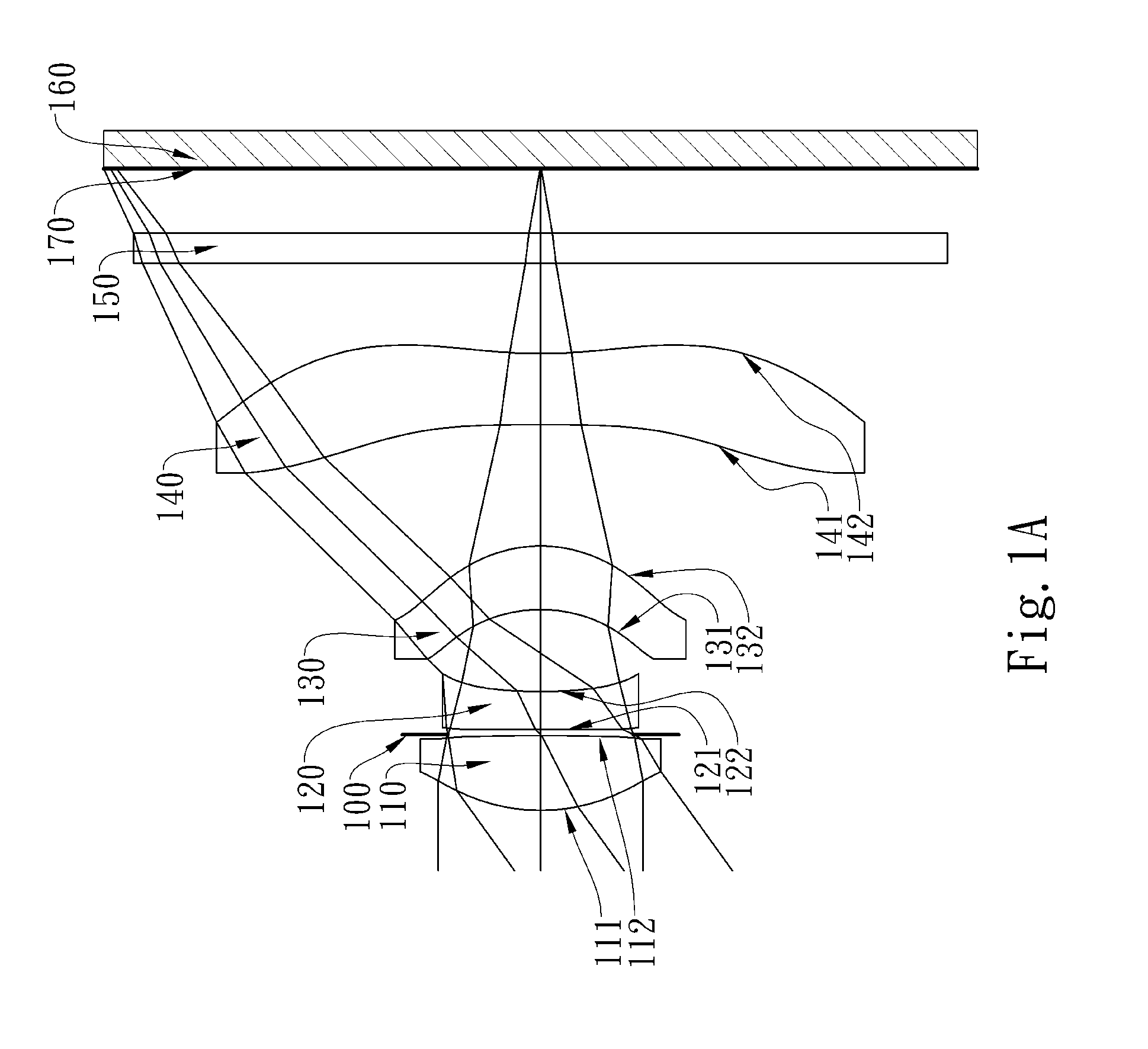
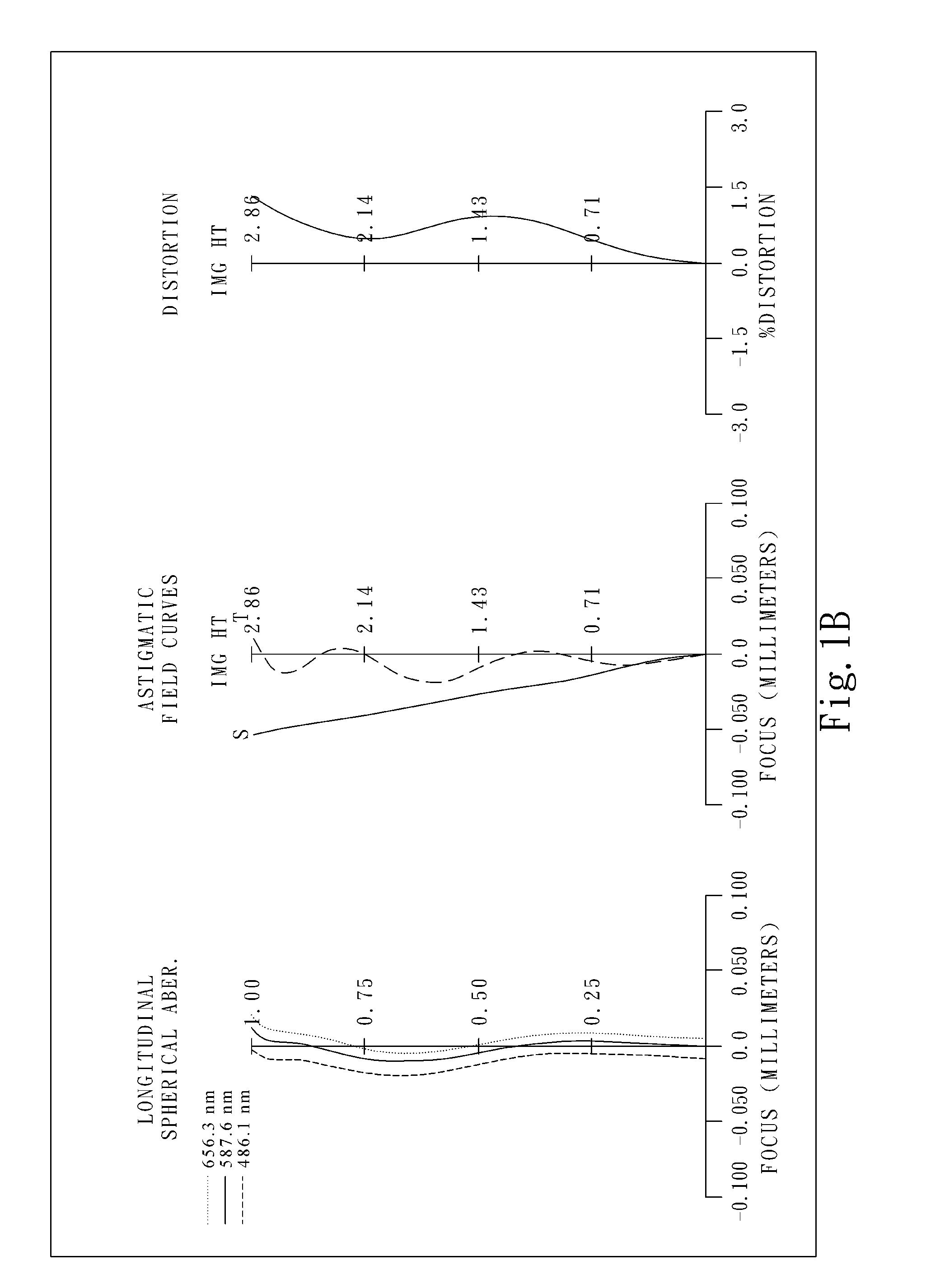
[0066]FIG. 1A shows an image capturing lens system in accordance with the first embodiment of the present invention, and FIG. 1B shows the aberration curves of the first embodiment of the present invention. The image capturing lens system of the first embodiment of the present invention mainly comprises four non-cemented lens elements, in order from an object side to an image side:

[0067]a first lens element 110 made of plastic with positive refractive power having a convex object-side surface 111 and a convex image-side surface 112, the object-side and image-side surfaces 111 and 112 thereof being aspheric;

[0068]a second lens element 120 made of plastic with negative refractive power having a concave object-side surface 121 and a concave image-side surface 122, the object-side and image-side surfaces 121 and 122 thereof being aspheric;

[0069]a third lens element 130 made of plastic with positive refractive power having a concave object-side surface 131 and a convex image-side surface...

embodiment 2

[0094]FIG. 2A shows an image capturing lens system in accordance with the second embodiment of the present invention, and FIG. 2B shows the aberration curves of the second embodiment of the present invention. The image capturing lens system of the second embodiment of the present invention mainly comprises four non-cemented lens elements, in order from an object side to an image side:

[0095]a first lens element 210 made of plastic with positive refractive power having a convex object-side surface 211 and a convex image-side surface 212, the object-side and image-side surfaces 211 and 212 thereof being aspheric;

[0096]a second lens element 220 made of plastic with negative refractive power having a concave object-side surface 221 and a concave image-side surface 222, the object-side and image-side surfaces 221 and 222 thereof being aspheric;

[0097]a third lens element 230 made of plastic with positive refractive power having a concave object-side surface 231 and a convex image-side surf...

embodiment 3

[0103]FIG. 3A shows an image capturing lens system in accordance with the third embodiment of the present invention, and FIG. 3B shows the aberration curves of the third embodiment of the present invention. The image capturing lens system of the third embodiment of the present invention mainly comprises four non-cemented lens elements, in order from an object side to an image side:

[0104]a first lens element 310 made of plastic with positive refractive power having a convex object-side surface 311 and a convex image-side surface 312, the object-side and image-side surfaces 311 and 312 thereof being aspheric;

[0105]a second lens element 320 made of plastic with negative refractive power having a concave object-side surface 321 and a concave image-side surface 322, the object-side and image-side surfaces 321 and 322 thereof being aspheric;

[0106]a third lens element 330 made of plastic with positive refractive power having a concave object-side surface 331 and a convex image-side surface...


PUM


Abstract

This invention provides an image capturing lens system in order from an object side to an image side comprising four non-cemented lens elements with refractive power: a first lens element with positive refractive power having a convex object-side surface; a second lens element with negative refractive power having a concave image-side surface; a plastic third lens element having a concave object-side surface and a convex image-side surface, both the object-side and image-side surfaces thereof being aspheric; and a plastic fourth lens element with negative refractive power having a concave image-side surface, both the object-side and image-side surfaces thereof being aspheric, and at least one inflection point is formed on at least one of the object-side and image-side surfaces thereof; wherein the image capturing lens system comprises a stop positioned between the first lens element and the second lens element.

Description

CROSS-REFERENCE TO RELATED APPLICATIONS[0001]This non-provisional application claims priority under 35 U.S.C. §119(a) on Patent Application No. 100132823 filed in Taiwan, R.O.C. on Sep. 13, 2011, the entire contents of which are hereby incorporated by reference.BACKGROUND OF THE INVENTION[0002]1. Field of the Invention[0003]The present invention relates to an image capturing lens system, and more particularly, to a compact image capturing lens system used in electronic products.[0004]2. Description of the Prior Art[0005]In recent years, with the popularity of portable electronic products having photographing function, the demand of compact imaging lens system has grown. Generally, the sensor of a general photographing camera is none other than CCD (Charge Coupled Device) or CMOS device (Complementary Metal Oxide Semiconductor device). Furthermore, advances in semiconductor manufacturing technology have allowed the pixel size of sensors to be reduced and therefore lead compact imagin...

Claims


Application Information

Patent Timeline
Patent Type & Authority Applications(United States)
IPC IPC(8): G02B13/18
CPCG02B9/34G02B13/004
Inventor HSU, CHIH-WENTSAI, TSUNG-HANCHOU, MING-TA
Owner LARGAN PRECISION
Why Eureka
Try Eureka