
Digital hydraulic system

a control system and hydraulic technology, applied in soil shifting machines/dredgers, mechanical equipment, transportation and packaging, etc., can solve the problems of no means by which a prime mover is governed to add energy, work implement gains significant potential energy, etc., to achieve maximum efficiency, optimize energy utilization in a work machine, and avoid intentional waste of energy.

Inactive Publication Date: 2013-03-14
DIGITAL HYDRAULICS
View PDF5 Cites 3 Cited by
  • Summary
  • Abstract
  • Description
  • Claims
  • Application Information

AI Technical Summary

Benefits of technology

The present invention optimizes energy usage in work machines, reducing energy waste. It can also be used in four quadrant operation and requires less cooling of hydraulic fluid.

Problems solved by technology

As the work implement may be relatively heavy, the work implement gains significant potential energy when raised to the elevated position.
Typically, however, there are no means by which a prime mover is governed to add energy only up to a pressure level less than a preset supply pressure.

Method used


Image

  • Digital hydraulic system
  • Digital hydraulic system
  • Digital hydraulic system

Examples


Embodiment Construction

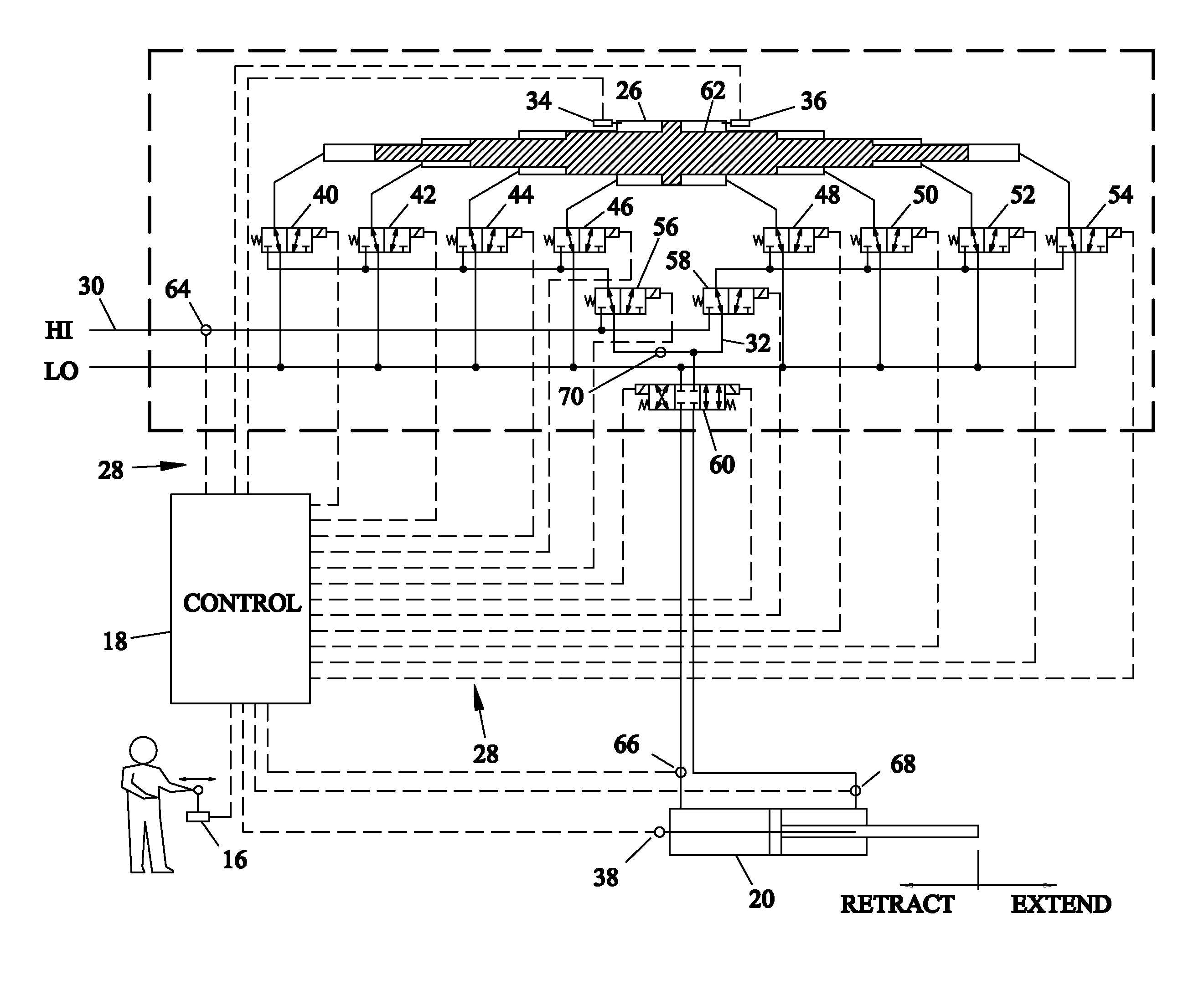
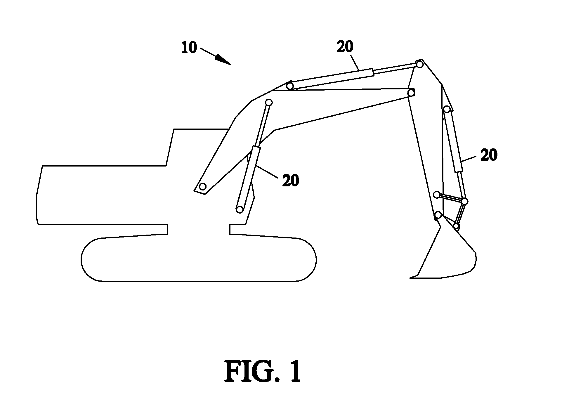
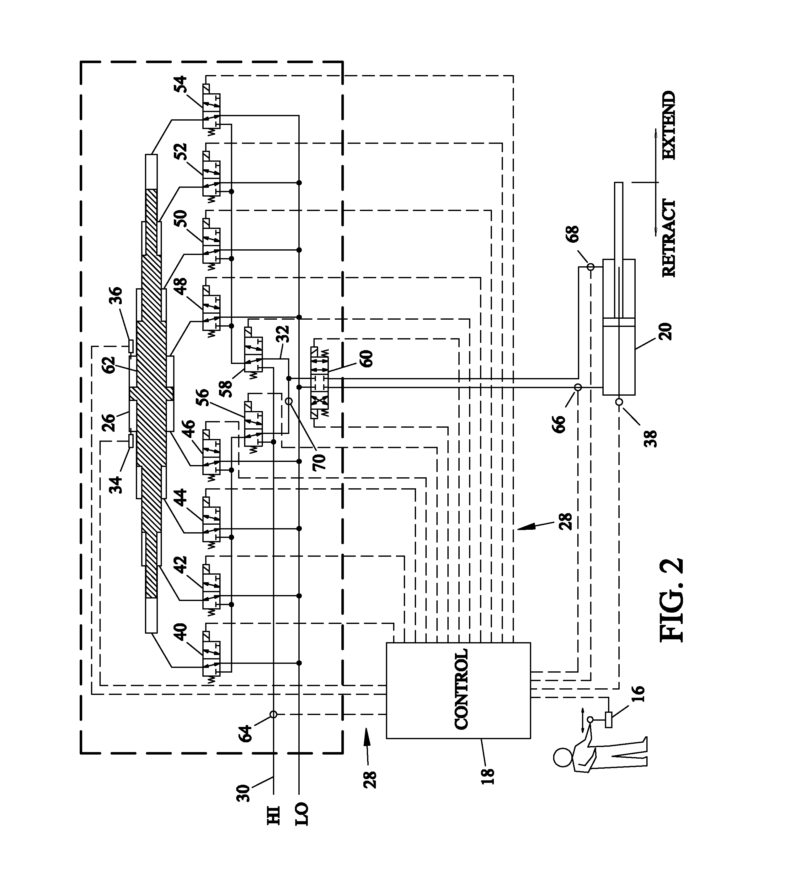
[0035]Referring now to the drawings, and more particularly to FIGS. 1-3, there is shown a digital hydraulic system 10 being used in conjunction with a backhoe assembly. Digital hydraulic system 10 includes a power source 12, a pump 14, a human interface 16, a control system 18, an actuator 20, a buffering device 22, an accumulator 24, a digital hydraulic transformer 26, sense and control lines 28 and hydraulic lines 30 and 32. Power source 12 provides mechanical power to actuate pump 14 to serve as a hydraulic source to provide pressurized fluid / flow to digital hydraulic system 10. Pump 14 can be a typical hydraulic pump or may be a digital hydraulic pump 14 as described herein. Buffering device 22 serves an anti-cavitation function to absorb any impulses that may occur as the hydraulic fluid is switched by control system 18. Additionally, buffering device 22 may serve an accumulation function. Although not illustrated, pump 14 and actuator 20 may have buffering devices associated w...


PUM


Abstract

A digital hydraulic system including a fluid having three portions each at a pressure and a digital hydraulic transformer having a first and second element. The first element has a first end and a second end. The first and second elements operating along a common axis, and together defining at least four variable volume working chambers. The at least two of the at least four variable volume working chambers containing fluid directing force on the second element in a direction toward the first end. Another two of the at least four variable volume working chambers containing fluid directing force on the second element toward the second end. A control system individually selectively fluidically connects and disconnects each of the four variable volume working chambers to and from the three portions of the fluid at the three pressures.

Description

CROSS REFERENCE TO RELATED APPLICATIONS[0001]This is a divisional of U.S. patent application Ser. No. 12 / 352,398, entitled “DIGITAL HYDRAULIC SYSTEM”, filed Jan. 12, 2009, which is incorporated herein by reference, which was a continuation-in-part of U.S. patent application Ser. No. 11 / 564,065, entitled “DIGITAL HYDRAULIC SYSTEM”, filed Nov. 28, 2006, which is incorporated herein by reference. U.S. patent application Ser. No. 11 / 564,065 was a non-provisional application based upon U.S. provisional patent application Ser. No. 60 / 740,345, entitled “DIGITAL HYDRAULIC SYSTEM”, filed Nov. 29, 2005.BACKGROUND OF THE INVENTION[0002]1. Field of the Invention[0003]The present invention relates to a control system for a hydraulic work machine, and more particularly the present invention relates to the monitoring of potential and kinetic energies in movable elements of a hydraulic work machine, and to the control of hydraulic energy added to the hydraulic system.[0004]2. Description of the Rel...

Claims


Application Information

Patent Timeline
Patent Type & Authority Applications(United States)
IPC IPC(8): F16L55/00
CPCF16L55/00E02F9/123E02F9/2217F15B2211/7053F15B2211/214F15B2211/6346F15B3/00Y10T137/598
Inventor BISHOP, ELTON D.
Owner DIGITAL HYDRAULICS
Learn More