
Measuring instrument

Active Publication Date: 2013-03-07
MITUTOYO CORP
View PDF9 Cites 6 Cited by
  • Summary
  • Abstract
  • Description
  • Claims
  • Application Information

AI Technical Summary

Benefits of technology

The invention aims to solve problems with visibility in measuring instruments by improving them. It aims to reduce production costs by designing a more efficient measuring instrument.

Problems solved by technology

As described above, since the displays of typical measuring instruments employ LCDs of designs dedicated for each of the measuring instruments, it is difficult to use the display in common with each of the measuring instruments.
Further, when the display design is to be changed, the LCD has to be re-designed and re-manufactured, so that the production cost increases.
Further, the LCD used for the display of measuring instruments provides narrow view angle (approximately 40 degrees), the LCD is poor in visibility according to the angle to be viewed.
Especially, it is difficult to read the displayed information in a dark area in a factory and the like.

Method used


Image

  • Measuring instrument
  • Measuring instrument
  • Measuring instrument

Examples


first exemplary embodiment

Arrangement of Measuring Instrument

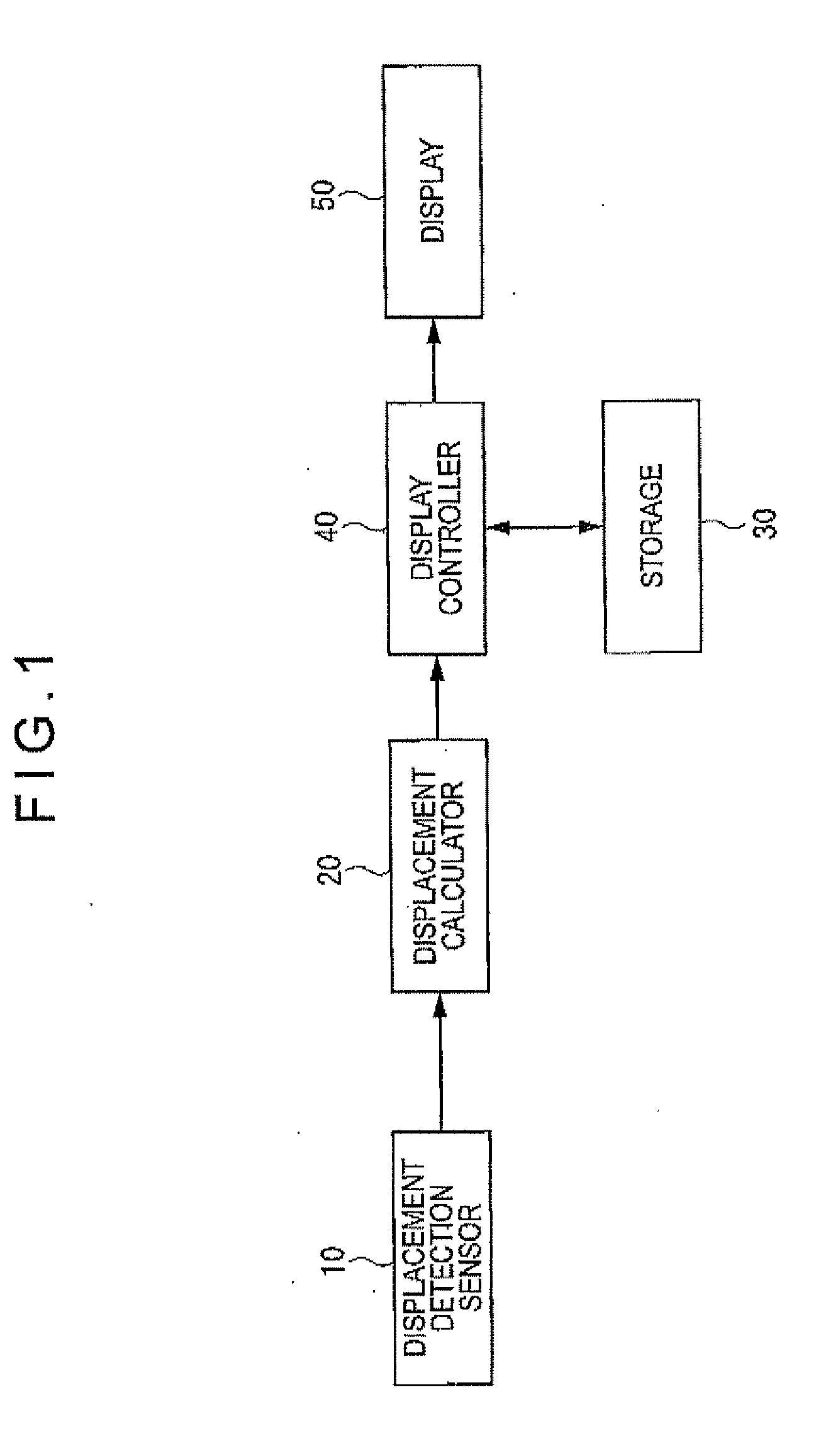
[0061]FIG. 1 illustrates a measuring instrument according to a first exemplary embodiment.

[0062]The measuring instrument includes a displacement detection sensor 10, a displacement calculator 20, a storage 30, a display controller 40 and a display 50.

[0063]Herein, the measuring instrument refers to a measuring instrument including a movable member that is movable relative to a body and measuring a dimension of an object to be measured based on a displacement of the movable member (e.g. a vernier caliper, micrometer and indicator (dial gauge)).

[0064]The displacement detection sensor 10 detects a displacement of the movable member of the measuring instrument. For instance, a vernier caliper shown in FIG. 16 detects a displacement of a slider 2 (movable member) relative to a main scale 1 (main body). A micrometer shown in FIG. 17 detects a displacement of a spindle 4 (movable member) relative to a main body 3. Further, an indicator shown in FIG. 18 de...

second exemplary embodiment

[0086]FIG. 4 illustrates a measuring instrument according to a second exemplary embodiment. In the description of the second exemplary embodiment, the same components as those in the first exemplary embodiment will be denoted by the same reference numerals and explanation thereof will be omitted.

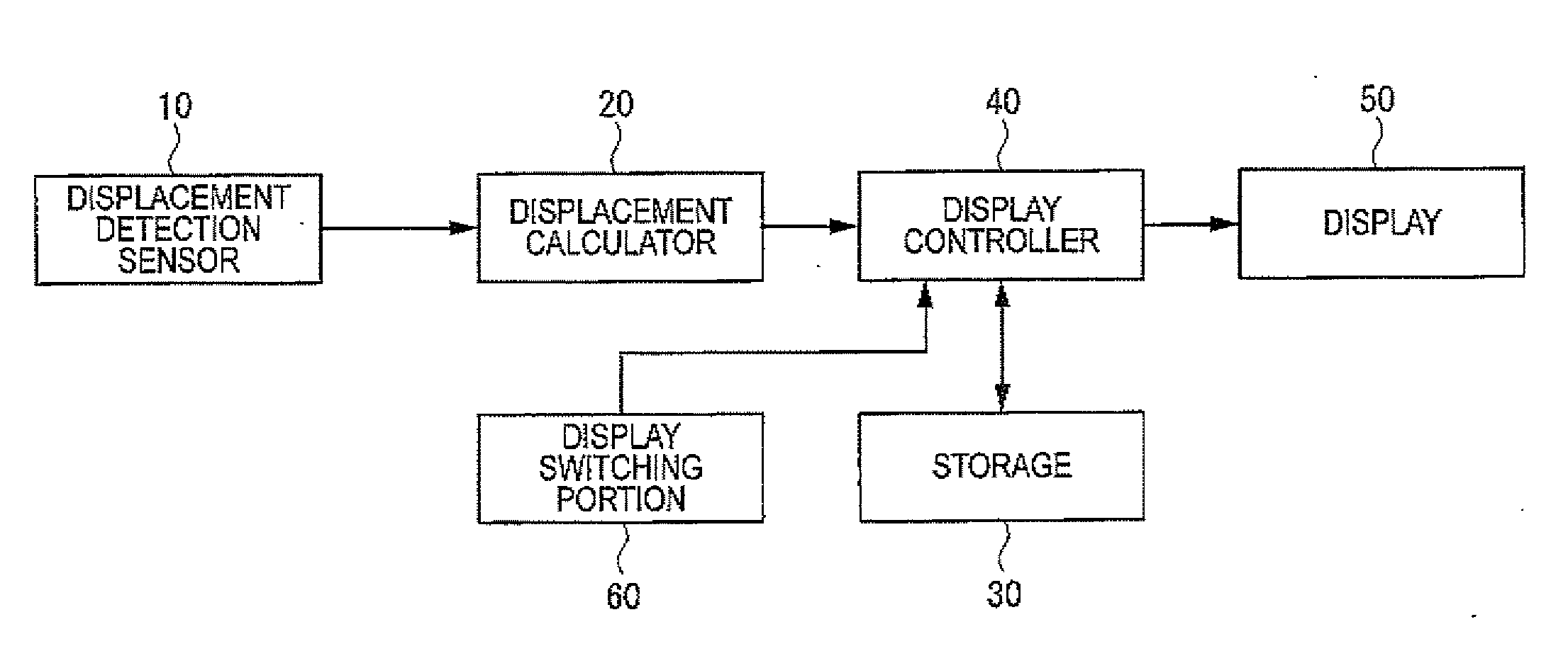
[0087]The measuring instrument is an example in which the invention is applied in a form of a display of a dial gauge. As in the measuring instrument in the first exemplary embodiment, the measuring instrument includes a displacement detection sensor 10, a displacement calculator 20, a storage 30, a display controller 40, a display 50 and a display switching portion 60.

[0088]The storage 30 of the second exemplary embodiment stores: a first display mode data for displaying the measurements as a numerical image and a plurality of scale segment images arranged in a circle, and simultaneously reversely displaying the scale segment images corresponding to an angular range in accordance with the m...


PUM


Abstract

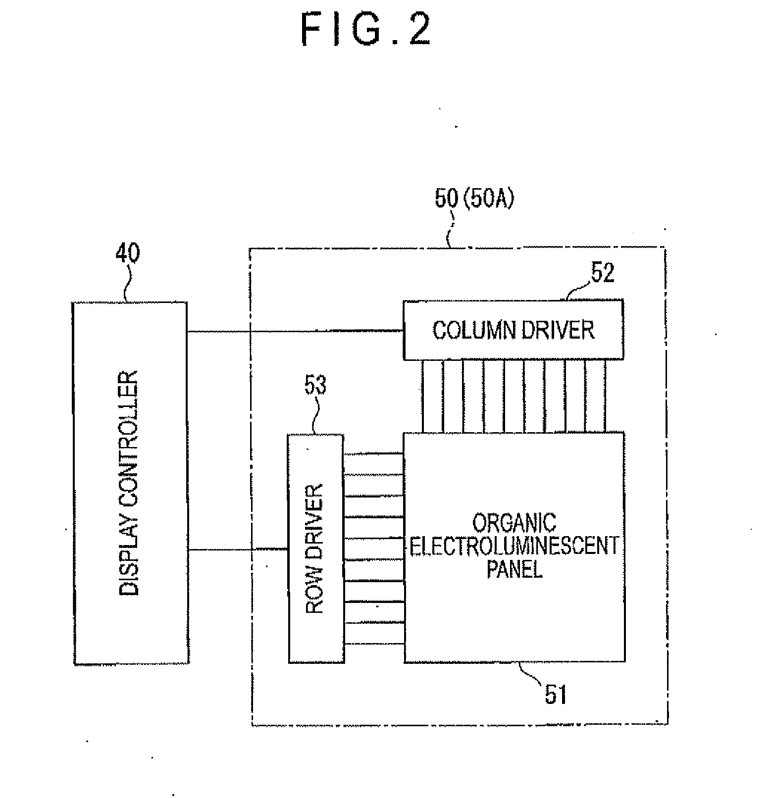
A measuring instrument includes a display that displays measurements. The display is provided by an organic electroluminescent display device or an electronic paper including an assembly of organic EL (Electro-Luminescence) devices. Since the display is provided by the organic electroluminescent display device or an electronic paper including an assembly of organic electroluminescence devices, visibility of the display can be enhanced. Further, since the display can be used for various measuring instruments in common and the display design can be easily changed, production cost can be reduced.

Description

[0001]The entire disclosure of Japanese Patent Applications No. 2011-492931 filed Sep. 5, 2011 and No. 2012-484384 filed Aug. 23, 2012 is expressly incorporated by reference herein.BACKGROUND OF THE INVENTION[0002]1. Field of the Invention[0003]The present invention relates to a measuring instrument. More specifically, the present invention relates to a measuring instrument including a display on which measurements are displayed.[0004]2. Description of the Related Art[0005]Some of measuring instruments for measuring distance, length and the like employ a display of LCDs (Liquid Crystal Displays) for displaying the measurements, the LCDs being respectively designed for each of the measuring instruments (see Literature 1 (JP-A-2007-78411).[0006]For instance, as shown in FIG. 16, a display of a vernier caliper has a numeral-display area 100 including five digits of seven-segment display elements and an inch / millimeter display area 101 displaying “in mm.”[0007]As shown in FIG. 17, a dis...

Claims


Application Information

Patent Timeline
IPC IPC(8): G01B5/00
CPCG01B3/002G01B3/18G01D7/06G01B3/22G01B3/205
Inventor HAYASHI, NOBUYUKISHIRAISHI, YOSHIAKIHAYASHIDA, SHUJIKIWADA, TAKEFUMI
Owner MITUTOYO CORP
Learn More