
Variable radius lever arm assembly

Inactive Publication Date: 2010-11-04
MALTBY MALORY
View PDF16 Cites 2 Cited by
  • Summary
  • Abstract
  • Description
  • Claims
  • Application Information

AI Technical Summary

Benefits of technology

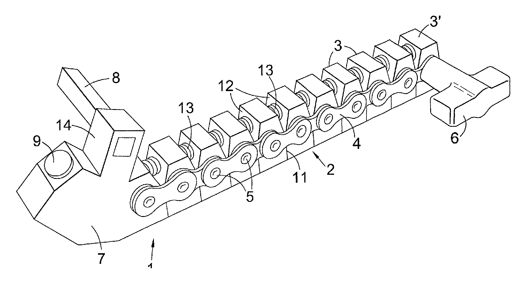
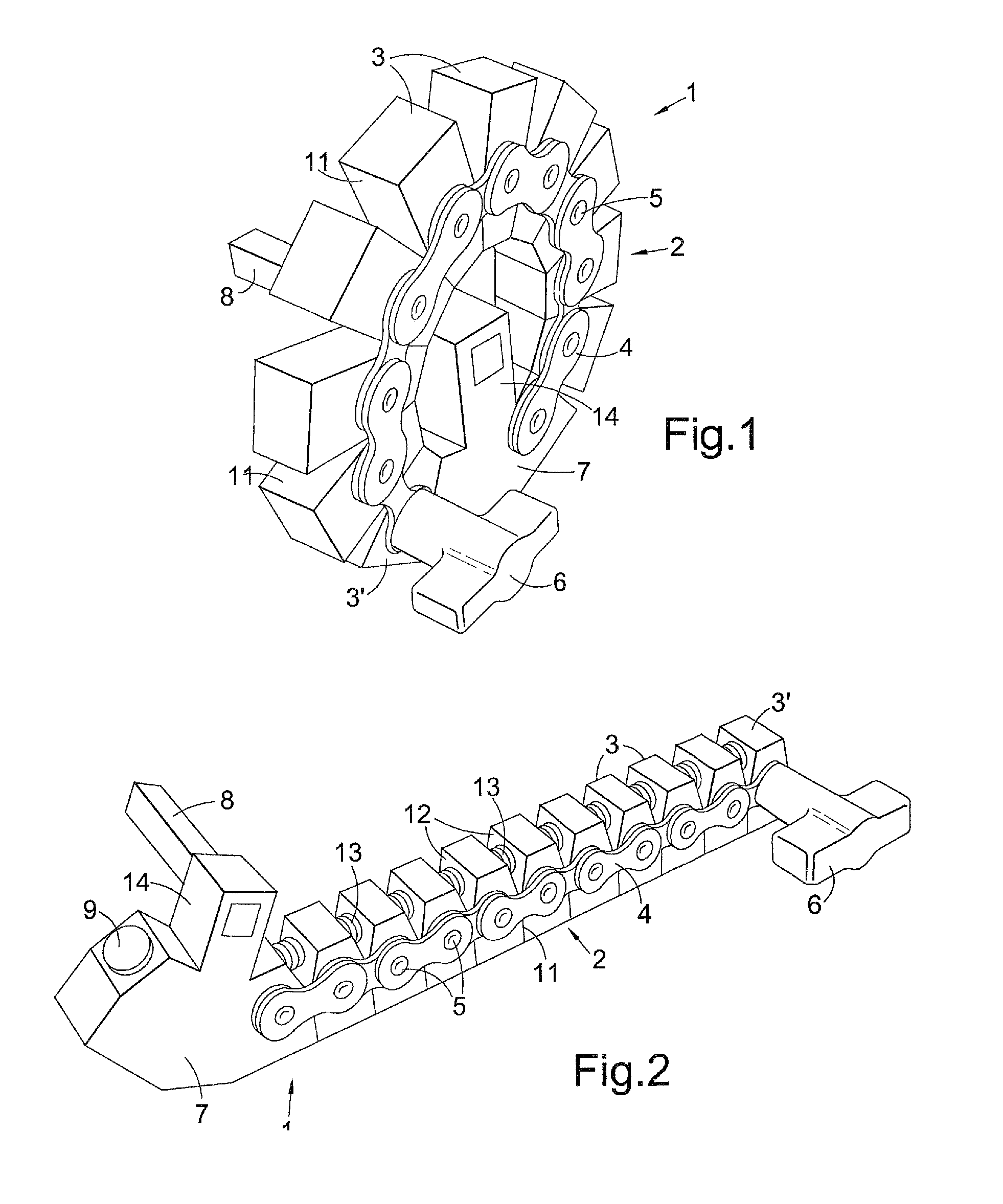
[0006]To greatly enhance turning operation for various different applications, preferably the distal end of the lever arm has a manually operable drive lug and wherein the drive lug is substantially perpendicular to the plane in which the arm curls.
[0019]The lever arm assembly may also be assembled as a wheel valve, gate valve or other wheel driven apparatus, suitably wheel driven apparatus that has a rotary wheel to move an element with high static friction, the wheel incorporating the lever arm assembly built into the circumference thereof. For fire hydrant wheel valves or other water or fuel flow control valves that need to be opened or shut in emergency situations this can avoid need to find a crow bar to lever open the wheel valve and can be a life-saver.
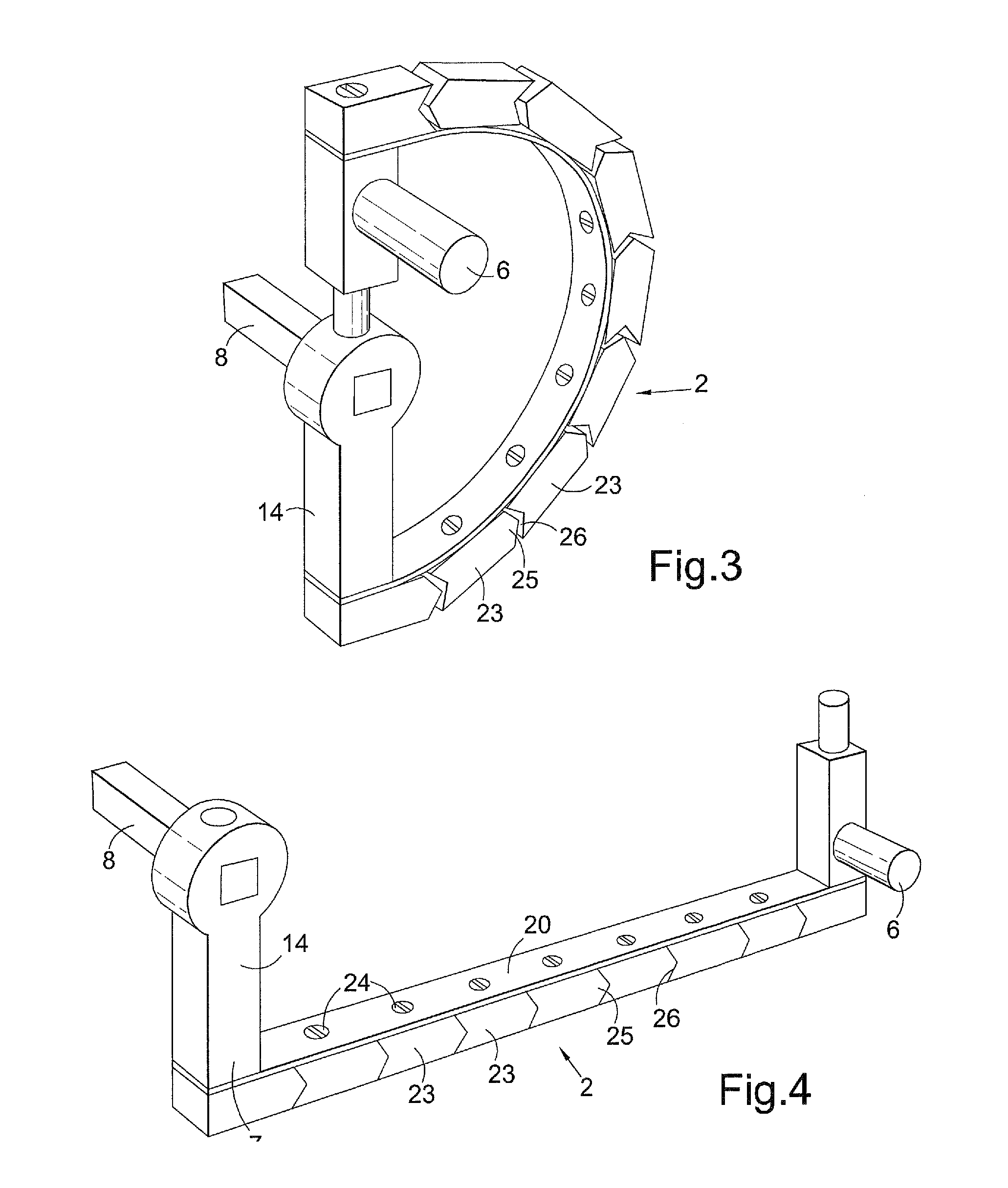
[0020]In any of the embodiments the assembly may further have a load cell between two adjacent segments blocks of the lever arm, the load cell being arranged to sense the force of pressing together of the two adjacent segments / blocks as the lever is applied in use. The apparatus can thus serve as a torque wrench. The load cell may be provided with a processor and display on the lever arm to provide a local read-out of the torque at the lever arm though this is not ideal for ease of reading since the lever arm is being turned in use. Instead preferably the lever arm assembly may have means to link, suitably wirelessly, to a remote processor and display such as a desk-top or laptop computer or Smartphone or other device to provide the read-out in a more easily read manner.

Problems solved by technology

These devices do not provide for any substantial adjustment of the length of the lever handle for adjusting leverage.

Method used


Image

  • Variable radius lever arm assembly
  • Variable radius lever arm assembly
  • Variable radius lever arm assembly

Examples


Embodiment Construction

[0036]The lever arm assembly 1 of FIGS. 1 and 2 comprises a lever arm 2 of variable effective length having a proximal end to connect to a driven member to be turned and a distal end having a handle for turning the lever arm 2. The lever arm 2 comprises a plurality of rigid blocks 3 articulated together by a chain 4, the link pivots 5 of which are affixed to the respective blocks 3. The end block 3′ at the distal end of the arm fixedly carries a drive lug in the form of a swivelling, pivotally mounted, handle 6 of T-shape that can be gripped by the fingers of the user so as to apply a turning force to the lever arm 2 and which swivels on the block 3′ as the lever arm 2 is turned. Handles of other shapes may be employed. Fixed (non-swivelling) handles may be employed for some embodiments but are generally less comfortable to use and are less efficient.

[0037]The opposite, proximal, end of the chain 4 is connected to a drive block 7 which carries a square drive spindle 8 used in this e...


PUM


Abstract

A curled variable radius lever comprises a lever arm 2 of variable effective length that curls and uncurls about a drive axis. In a preferred arrangement the lever assembly has a plurality of rigid blocks 3 articulated together by a chain 4 with link pivots 5 which are affixed to respective blocks 3. Each block 3 has a pair of facing walls 11 and a pair of facing mutually inclined sloping walls 12 which abut when the lever arm 2 is in a curled condition. The lever arm 2 is pulled into the curled condition by a coiled tension spring 13 and restrained in this position by a magnet 9. When it is uncurled the walls 11 abut. The chain 4 then prevents the arm 2 from bending further when a driving force is applied by users to a handle 6. The lever may be used with socket sets, yacht winch, fishing rod reel, a bicycle crank or a jack assembly.

Description

FIELD OF THE INVENTION[0001]This invention relates to a lever arm assembly of variable radius. The unique features of the assembly make it suitable for a wide variety of uses including, inter alia, in a yacht winch, in a fishing rod reel, as a lever for a socket set, in a bicycle crank assembly, in a jack assembly, in a torque wrench and as part of a wheel valve assembly.BACKGROUND TO THE INVENTION[0002]There are circumstances in which it would be desirable to be able to alter the effective length of a manually operable lever arm. Two constructions for adjusting the length of a lever arm are shown in U.S. Pat. No. 4,582,298 and in US patent application US20060196303A1. U.S. Pat. No. 4,582,298 discloses a yacht winch assembly in which the winch crank arms are telescopic to permit the arms to be increased in length by releasing a spring-biased catch which is capable of holding the arm in either a short or long condition. The user chooses whether to increase the winch arm length or to ...

Claims


Application Information

Patent Timeline
IPC IPC(8): G05G1/04
CPCB66D1/04G05G1/085F16H51/02Y10T74/206B66F13/00G05G1/04B66D2700/0116
Inventor MALTBY, MALORY
Owner MALTBY MALORY
Learn More