
Apparatus and method for diverting water at basement joints

a technology for water entering the basement and the basement, which is applied in the direction of foundation engineering, building components, construction, etc., can solve the problems of water entering the basement or the foundation of the building, a common but potentially very damaging and expensive problem, and the drain tile becomes clogged with soil and other particulates, and the footing tends to move away from the footing

Active Publication Date: 2013-02-28
DRY BASEMENT
View PDF53 Cites 7 Cited by
  • Summary
  • Abstract
  • Description
  • Claims
  • Application Information

AI Technical Summary

Benefits of technology

The system effectively diverts water from multiple entry points with minimal soil disruption, preventing radon leakage and maintaining consistent floor slab height, offering greater water diverting and carrying capacity compared to prior systems.

Problems solved by technology

Water entering a building's foundation or basement is a common but potentially very damaging and expensive problem.
Because water is naturally intermixed with sediment, and further due to the size of the perforations, the drain tile becomes clogged with soil and other particulates over time.
An additional problem with an installed drain tile is that it tends to move away from the footing over time.
Thus, when access to the drain tile is required for replacement or mending, the user does not necessarily know where to dig to locate the drain tile.
Displacement of the soil at this depth is undesirable, as it creates pockets or holes that potentially undermine the integrity of the footing.
Although the pipe receives water flowing down the interior face of the basement wall and along a top of the footing and under the basement wall, the pipe is insufficient for receiving water leaching upwards from the interior of the foundation.

Method used


Image

  • Apparatus and method for diverting water at basement joints
  • Apparatus and method for diverting water at basement joints
  • Apparatus and method for diverting water at basement joints

Examples


Embodiment Construction

[0024]The following detailed description of the invention references the accompanying drawings that illustrate specific embodiments in which the invention can be practiced. The embodiments are intended to describe aspects of the invention in sufficient detail to enable those skilled in the art to practice the invention. Other embodiments can be utilized and changes can be made without departing from the scope of the present invention. The following detailed description is, therefore, not to be taken in a limiting sense. The scope of the present invention is defined only by the appended claims, along with the full scope of equivalents to which such claims are entitled.

[0025]In this description, references to “one embodiment,”“an embodiment,” or “embodiments” mean that the feature or features being referred to are included in at least one embodiment of the technology. Separate references to “one embodiment,”“an embodiment,” or “embodiments” in this description do not necessarily refer...


PUM


Abstract

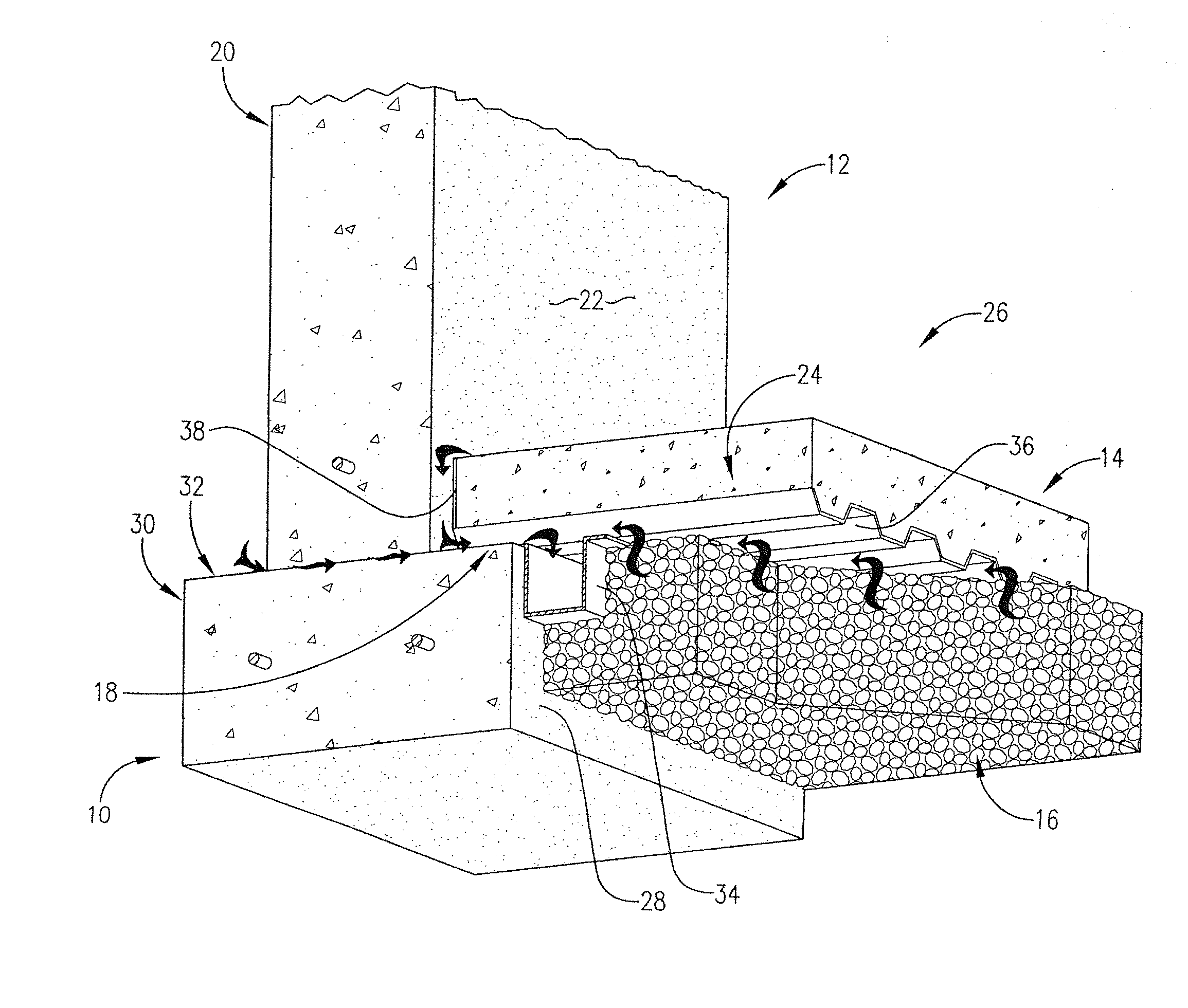
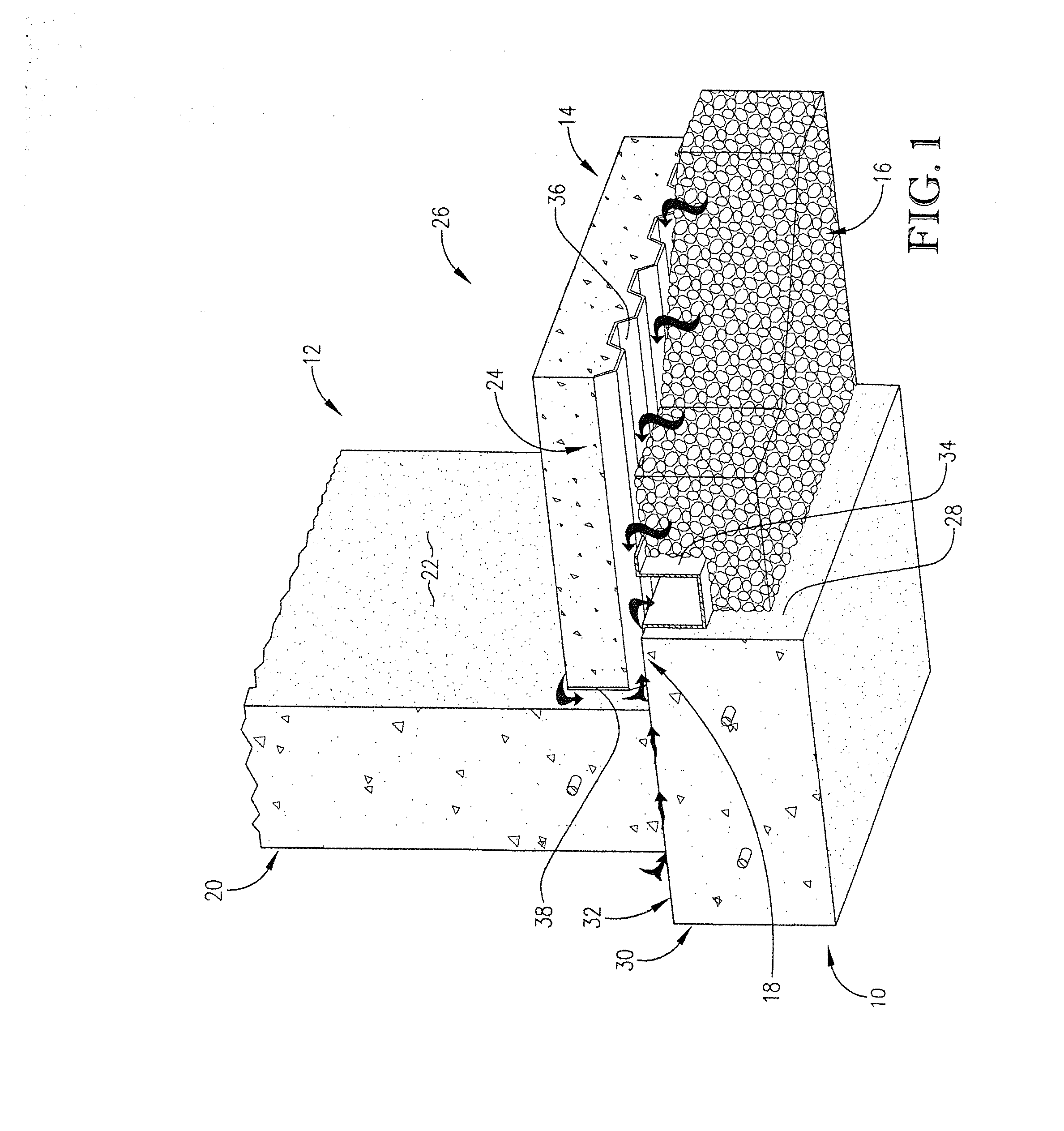
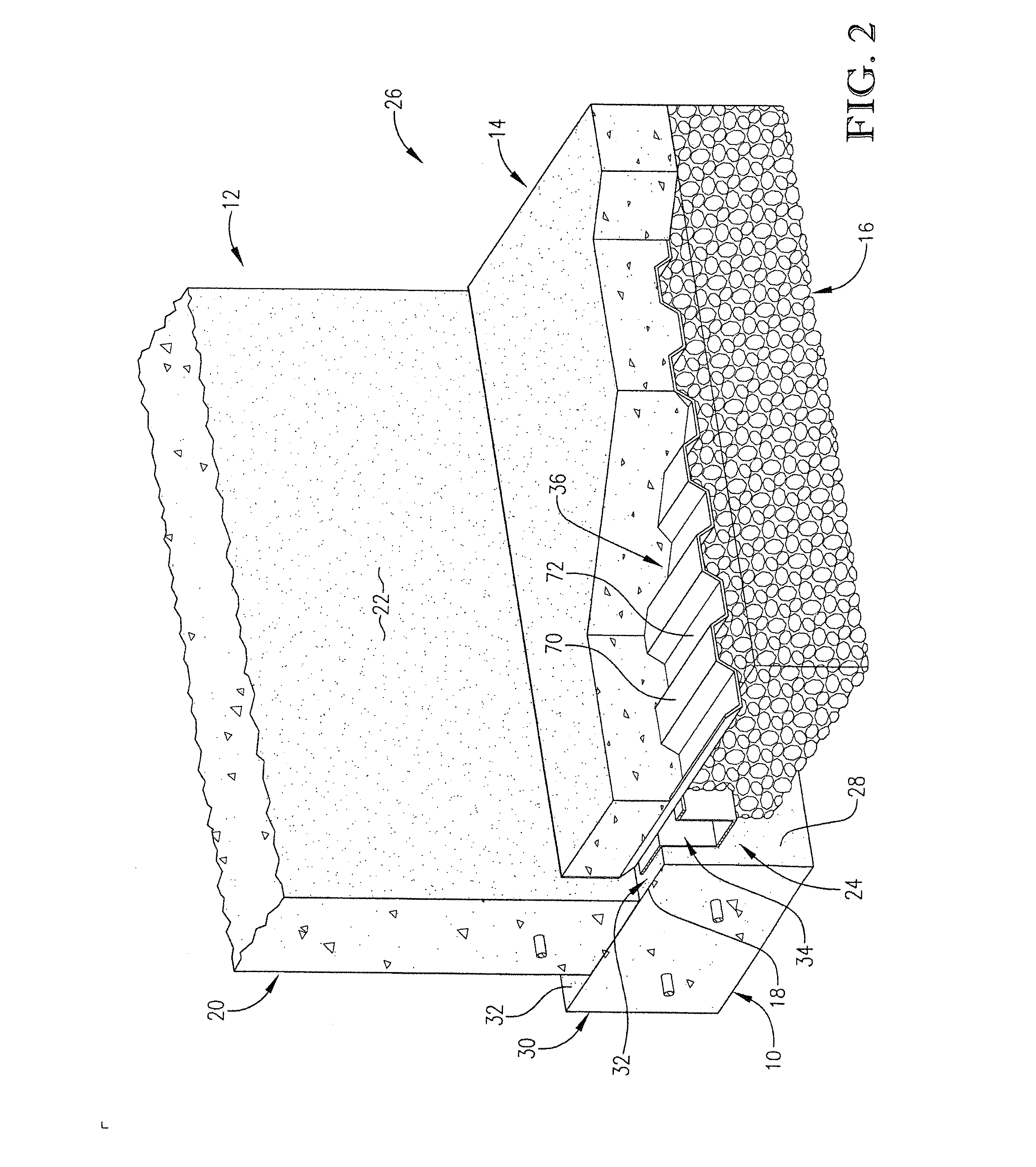
A water diverting system for diverting water from a building's foundation, where the foundation has a basement footing having an interior face oriented towards an interior of the foundation, a basement wall having an interior face oriented towards the interior of the foundation, and a basement floor slab. The system includes a channel for collecting water and configured to be installed adjacent the basement footing. The channel is overlaid with a corrugated track for directing water to the channel. A vertical water guide extends perpendicularly from the track and is positioned adjacent the interior face of the basement wall. The guide includes a plurality of spaced projections for directing water trickling down along the wall to the channel.

Description

RELATED APPLICATION[0001]This is a continuation application, and claims priority benefit with respect to all common subject matter, of U.S. patent application Ser. No. 12 / 980,601, filed Dec. 29, 2010, now U.S. Pat. No. 8,297,005, issued Oct. 30, 2012, and entitled “APPARATUS AND METHOD FOR DIVERTING WATER AT BASEMENT JOINTS.” The identified earlier-filed patent is hereby incorporated by reference in its entirety into the present application.BACKGROUND[0002]1. Field[0003]The present inventions relates to systems, apparatuses, and methods for collecting and diverting water from perimeter basement joints where water commonly collects.[0004]2. Related Art[0005]Water entering a building's foundation or basement is a common but potentially very damaging and expensive problem. Points of entry of the water occur at the intersection or joints of the basement footing 10, basement wall 12, and basement floor slab 14. Referring to FIG. 1, the footing 10 is concrete laid in the soil. Thus, the f...

Claims


Application Information

Patent Timeline
Patent Type & Authority Applications(United States)
IPC IPC(8): E02D19/18E04F17/00E04B1/70
CPCE02D31/002
Inventor BRAMBLE, CURTISFLECK, OTTO W.HICKMAN, LOWELL
Owner DRY BASEMENT
Learn More