
Wave technology

a wave technology and wave technology, applied in the field of footwear, can solve the problems of affecting the normal functioning of the human body, unable to effectively overcome the stresses encountered in everyday activities, and unable to achieve the effects of effective stress relief,

Active Publication Date: 2013-02-28
TBL LICENSING
View PDF7 Cites 83 Cited by
  • Summary
  • Abstract
  • Description
  • Claims
  • Application Information

AI Technical Summary

Benefits of technology

The present invention provides a shoe sole with a pattern of lugs that create a unique and comfortable shoe. The lugs are arranged in a repeating pattern that creates a wave pattern on the surface of the shoe. The first embodiment has a shoe sole with a first layer of material overlying a second layer of material, where the first layer has a higher hardness than the second layer. The second embodiment has a pattern of lugs that define a sinusoidal wave pattern, where each lug vertically compresses and then deflects in two directions. The third embodiment has a pattern of lugs that extend continuously from one side of the shoe to the other side. The pattern of lugs in the second and third embodiments create a shoe that is comfortable, stable, and provides a unique feel on the surface of the shoe.

Problems solved by technology

This is primarily because, while the human foot has existing natural cushioning characteristics, such natural characteristics are alone incapable of effectively overcoming the stresses encountered during everyday activity.
Trail running in particular can subject the foot and lower extremities to extreme conditions and therefore extreme loads.
Even in less demanding environments, such as in ordinary walking or road running, the human foot still experiences significant stresses.
Many traditional cushioning systems also suffer from the problem of preloading, due in part to the nature of such cushioning systems' design.
Specifically, a significant amount of existing cushioning systems utilize a continuous midsole in which each section of the midsole is susceptible to compression upon contact with the ground.
This results in large areas of the midsole being compressed at the time of ground contact, thus reducing cushioning potential and forcing the midsole to act as a monolithic structure.

Method used


Image

  • Wave technology
  • Wave technology
  • Wave technology

Examples


Embodiment Construction

[0027]In describing embodiments of the invention discussed herein, specific terminology will be used for the sake of clarity. However, the invention is not intended to be limited to any specific terms used herein, and it is to be understood that each specific term includes all technical equivalents, which operate in a similar manner to accomplish a similar purpose.

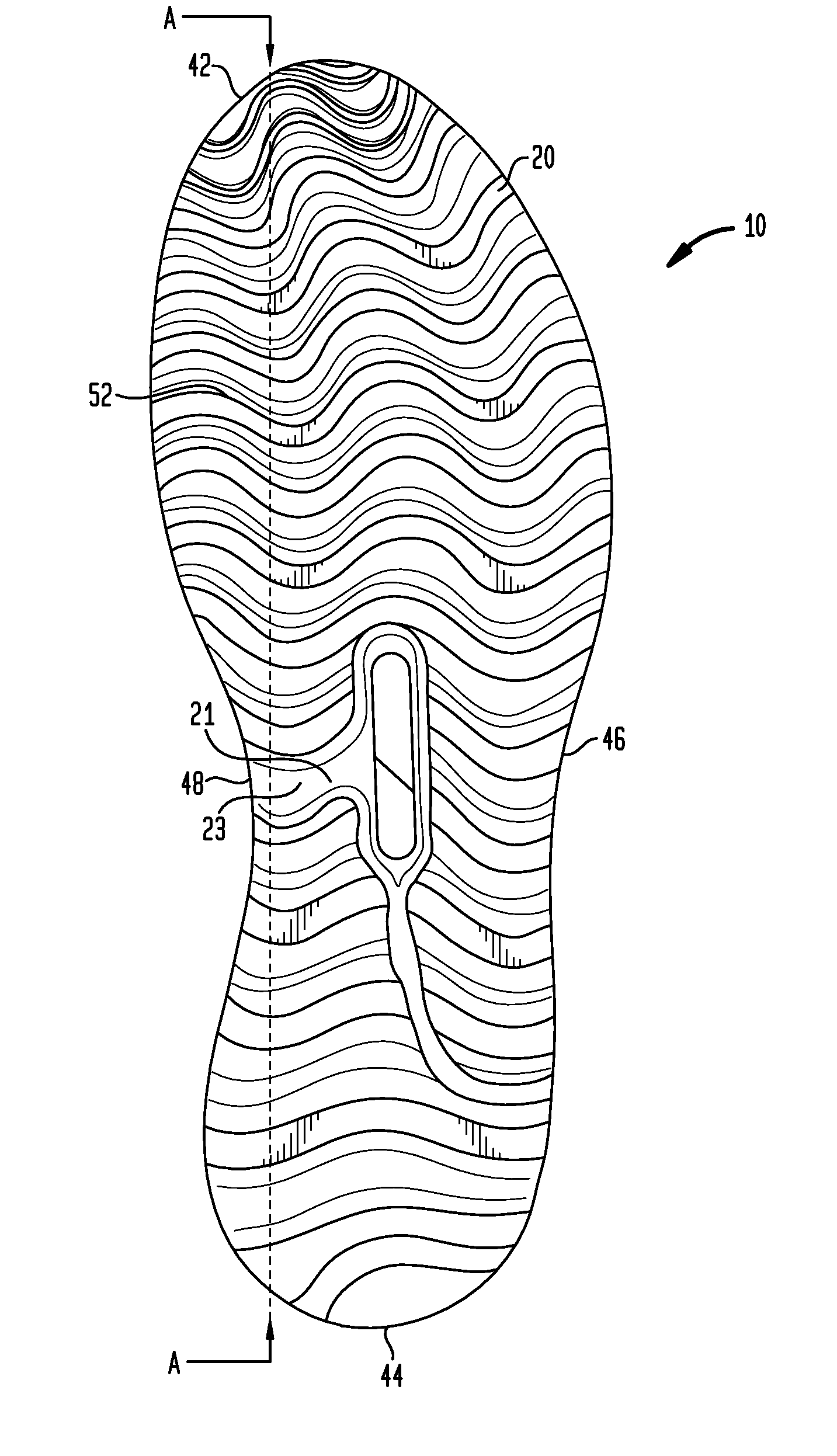
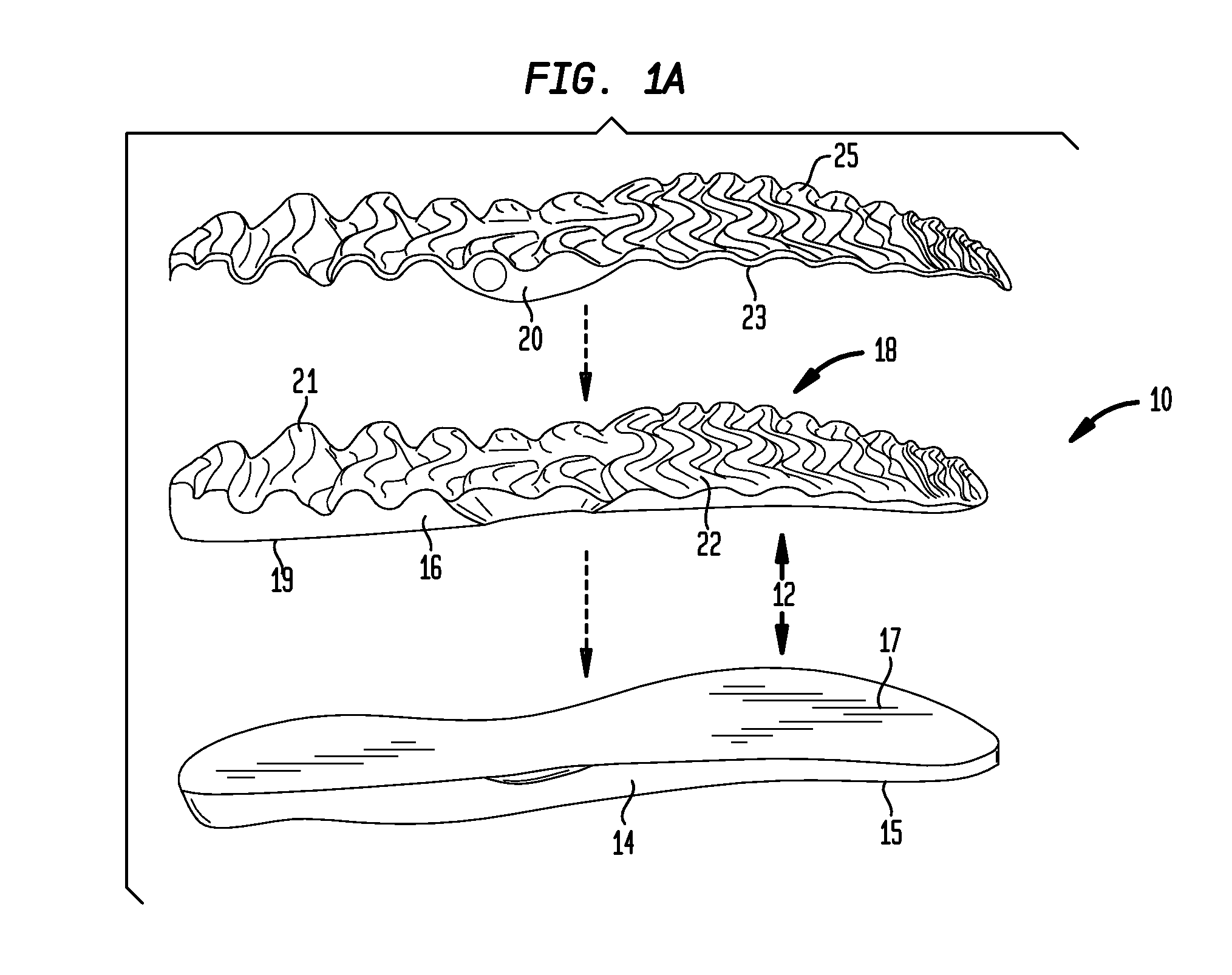
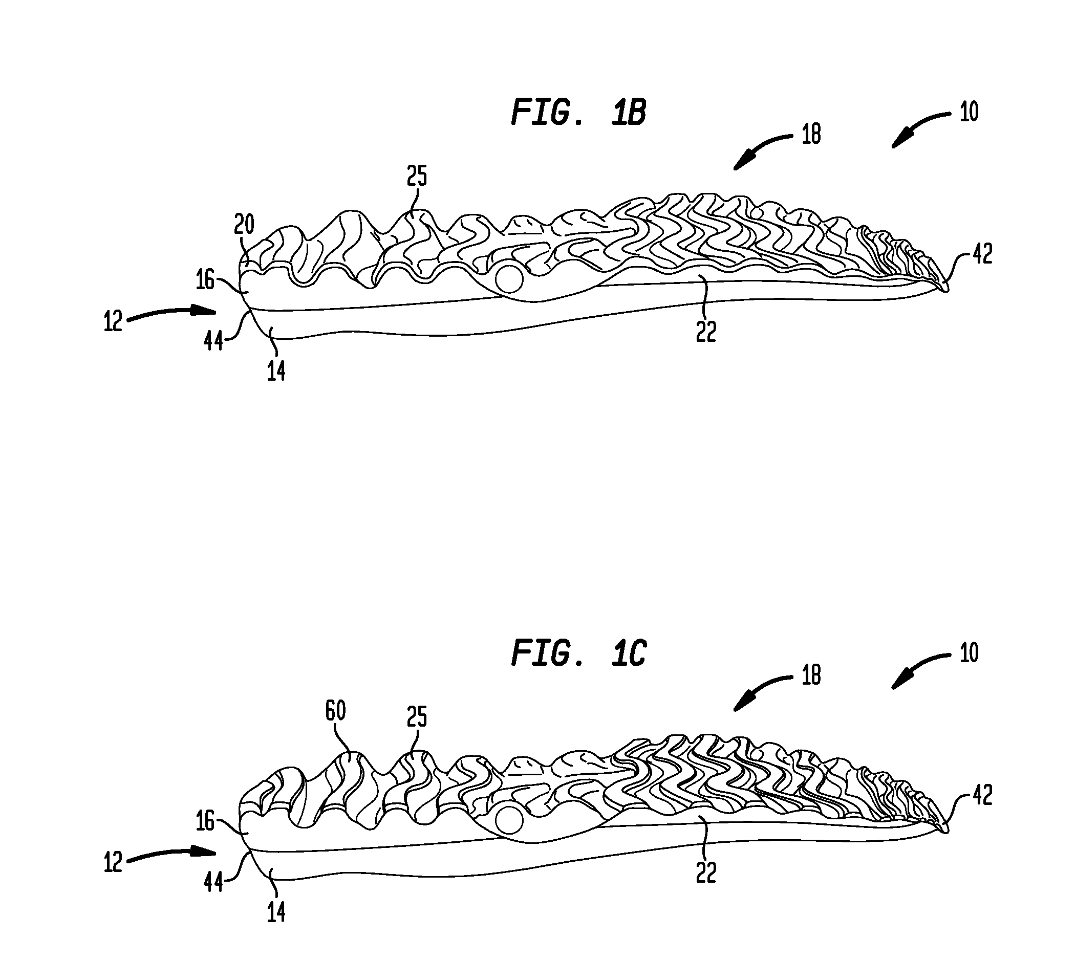
[0028]Referring to FIGS. 1A and 1B, a sole 10 for use with a shoe (not shown) includes a midsole 12 and an outsole 20, the outsole 20 being defined by a wave pattern 18 having a plurality of lugs 22, which allow for compression of the sole 10 in specific areas.

[0029]The midsole 12 of the sole 10 may include a first layer of material 14 and a second layer of material 16. In a particular embodiment, the first layer of material 14 and the second layer of material 16 may be completely solid. The first and second layers of material 14, 16, respectively, may also have corresponding top surfaces 15, 19 and bottom surfaces 17, 21....


PUM


Abstract

A shoe sole having improved cushioning characteristics is disclosed. The sole includes a midsole having a top layer of material and a bottom layer of material. In one embodiment, the top layer of material may be harder than the bottom layer of material. A pattern of lugs defining a wave may be formed on the bottom layer of material. The wave may generally be in the shape of sine wave so as to provide improved cushioning characteristics for the sole. An outsole may also be formed on the bottom layer of material and an upper may be connected to the top layer of material, such that a shoe is formed.

Description

BACKGROUND OF THE INVENTION[0001]The present invention relates to articles of footwear, and in particular to articles of footwear having a sole with improved cushioning characteristics.[0002]One of the primary focuses in the recent design of athletic footwear has been underfoot cushioning. This is primarily because, while the human foot has existing natural cushioning characteristics, such natural characteristics are alone incapable of effectively overcoming the stresses encountered during everyday activity. For example, an athlete may partake in an activity in which substantial loads are placed on the foot, joint, and muscular structures of the leg including the ankle, knee, and hip joints. Such activities include road running, track running, hiking or trail running. Trail running in particular can subject the foot and lower extremities to extreme conditions and therefore extreme loads. As one example, in trail running, as distinguished from track and road running, one might encoun...

Claims


Application Information

Patent Timeline
Patent Type & Authority Applications(United States)
IPC IPC(8): A43B13/12
CPCA43B13/122A43B13/187A43B13/127A43B13/12A43B13/14A43B13/18A43B13/223A43B5/00
Inventor HEALY, JOHNDILLON, PETERADAM, CHRISTOPHER
Owner TBL LICENSING
Learn More