
System, apparatus and method for deflecting a particle beam

a particle beam and apparatus technology, applied in the field of electromagnetic apparatus, can solve the problems of preventing system installation, reducing the efficiency of electromagnetic components, so as to achieve the effect of reducing the cost of installation and reducing the cost of operation

Active Publication Date: 2013-02-21
PYRAMID TECHN CONSULTANTS
View PDF5 Cites 24 Cited by
  • Summary
  • Abstract
  • Description
  • Claims
  • Application Information

AI Technical Summary

Problems solved by technology

These electromagnets should not occupy excessive space in the trajectory of the beam, as this may translate into a larger system, potentially higher costs, and may preclude the installation of systems in some locations.
Furthermore, beam aberrations introduced by the electromagnetic portions may be considered small.
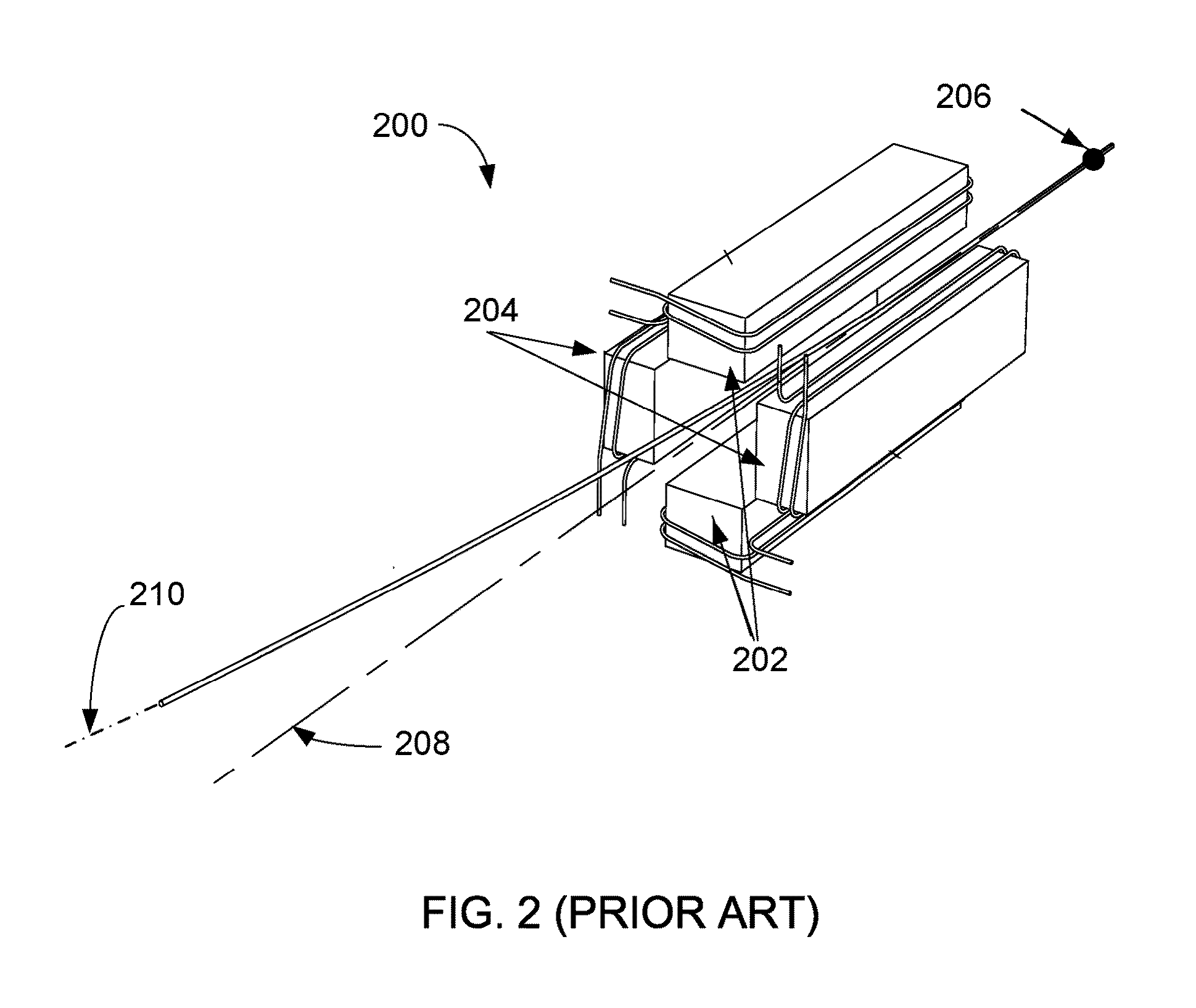
The increased air gap and increased amp-turns may result in more complexity for planning the map of potential beam positions due to differing speed of response of the in the horizontal and vertical axes.
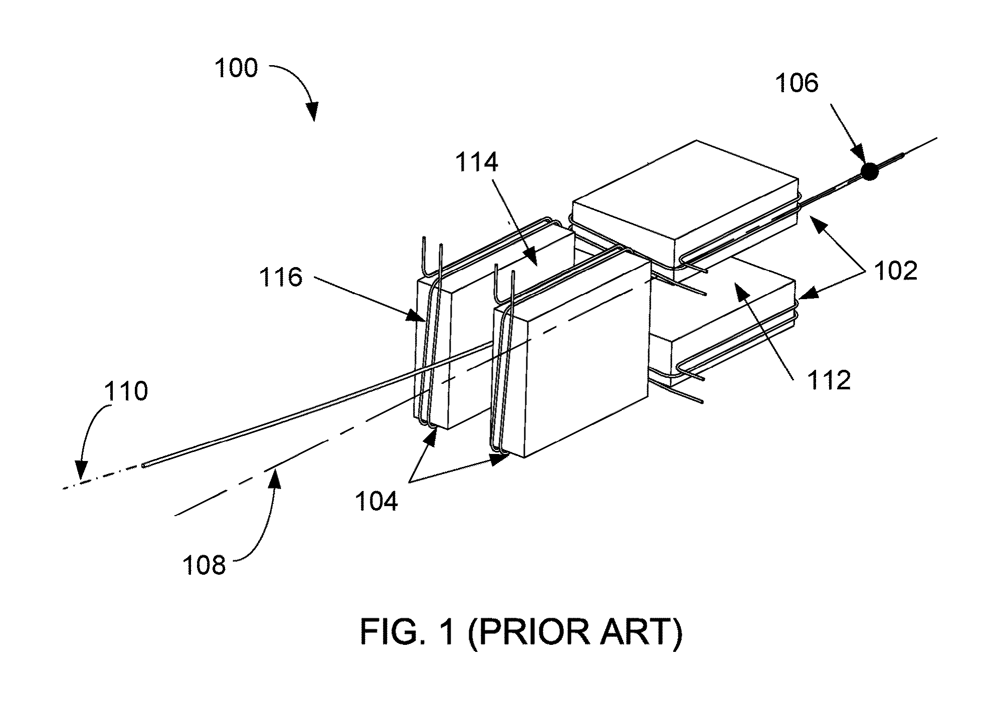
A square configuration for the electromagnetic portions is common, as other structures and configurations may result in a poor quality dipole magnetic field associated with the central axis and may also result in large pole spacing.
However, even a square configuration for the superimposed dipole may result in a magnetic field which may be of considerably less quality than realized with equivalent separate dipoles as illustrated with reference to FIG. 1.
Furthermore, as a result of the less quality magnetic field generated by the superimposed dipole, beam aberrations may be experienced.

Method used


Image

  • System, apparatus and method for deflecting a particle beam
  • System, apparatus and method for deflecting a particle beam
  • System, apparatus and method for deflecting a particle beam

Examples


Embodiment Construction

[0041]The present invention is best understood by reference to the detailed figures and description set forth herein.

[0042]Embodiments of the invention are discussed below with reference to the Figures. However, those skilled in the art will readily appreciate that the detailed description given herein with respect to these figures is for explanatory purposes as the invention extends beyond these limited embodiments. For example, it should be appreciated that those skilled in the art will, in light of the teachings of the present invention, recognize a multiplicity of alternate and suitable approaches, depending upon the needs of the particular application, to implement the functionality of any given detail described herein, beyond the particular implementation choices in the following embodiments described and shown. That is, there are numerous modifications and variations of the invention that are too numerous to be listed but that all fit within the scope of the invention. Also, ...


PUM


Abstract

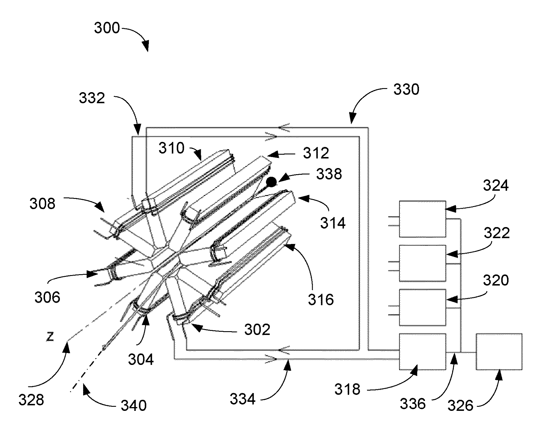
A variety of systems, apparatus and methods for deflecting a particle beam are described. An apparatus comprises at least six electromagnetic portions disposed on a plane. Each of the at least six electromagnetic portions is aligned with a radius emanating from an axis normal to the plane and is distanced from the axis to form a volume about the axis. At least six coils are configured for affecting a dipole magnetic field in the volume in response to electrical currents applied to physically opposing coils where a particle beam entering the volume is deflected. Each of the at least six coils is disposed about a one of the at least six electromagnetic portions. A yoke structure is configured for returning a generated magnetic flux.

Description

FEDERALLY SPONSORED RESEARCH OR DEVELOPMENT[0001]Not applicable.REFERENCE TO SEQUENCE LISTING, A TABLE, OR A COMPUTER LISTING APPENDIX[0002]Not applicable.COPYRIGHT NOTICE[0003]A portion of the disclosure of this patent document contains material that is subject to copyright protection. The copyright owner has no objection to the facsimile reproduction by anyone of the patent document or patent disclosure as it appears in the Patent and Trademark Office, patent file or records, but otherwise reserves all copyright rights whatsoever.FIELD OF THE INVENTION[0004]The present invention relates generally to implementations of electromagnetic apparatus. More particularly, the invention relates to delivering a charged particle beam to arbitrary points in a region, such as for particle therapy in medical applications.BACKGROUND OF THE INVENTION[0005]Many applications, including medical therapy and diagnostics, semiconductor processing and industrial radiography require beams of particles to ...

Claims


Application Information

Patent Timeline
Patent Type & Authority Applications(United States)
IPC IPC(8): H01J1/50
CPCH05H2007/046A61N2005/1087A61N5/1043G21K1/093
Inventor GORDON, JOHNBOISSEAU, RAYMOND PAULDART, ANDREW
Owner PYRAMID TECHN CONSULTANTS
Learn More